CREATING A MODBUS CONNECTION
The creation of a connection establishes a unidirectional (uplink) messaging transport link between ThingPark X IoT Flow and an embedded MODBUS slave. Values that come from your devices are mapped to MODBUS register values with the required mapping. Partners can connect to the MODBUS slave and poll the written registry values via their own MODBUS client implementations.
Two ways exist to publish a value to a register:
- Direct mapping: A data pointer is mapped to a register address of a slave ID.
- Templated mapping: A device type (for example, Milesight AM103) is mapped to a range of addresses. Another set of rules maps a device to a slave ID.
Creating a Connection From UI
You need to know the parameters that are required to perform this task.
- Click Connections -> Create -> ThingPark X IoT Flow.
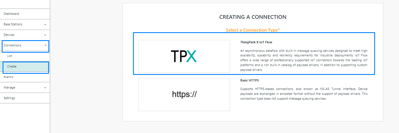
Then, a new page will open. Select the connection type : MODBUS.

- Fill in the form as in the example below and click on Create.
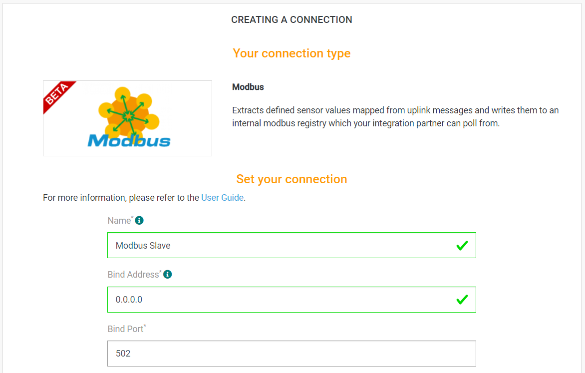
Parameters marked with * are mandatory.
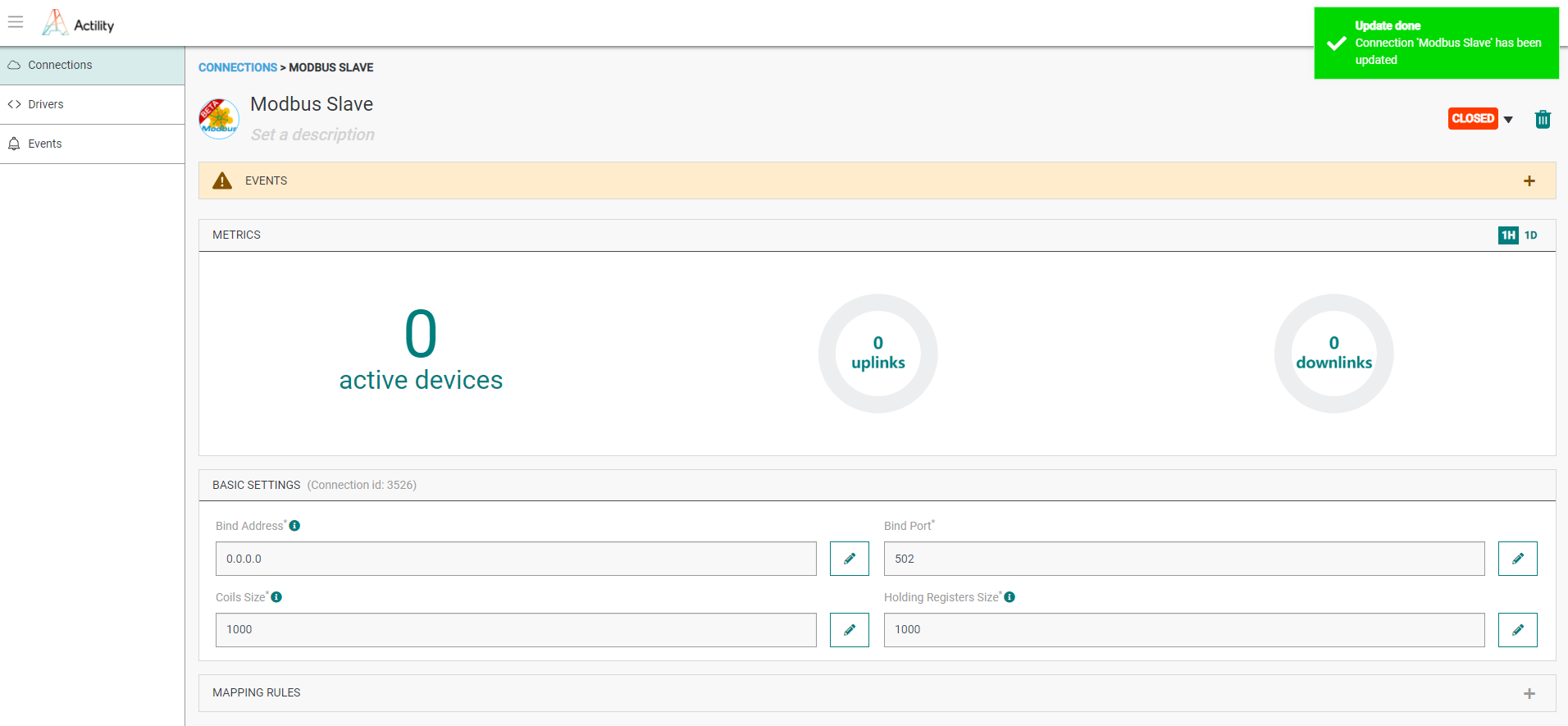
- A notification appears on the upper right side of your screen to confirm that the application has been created.

- After creating the application, you will be redirected to the application details.
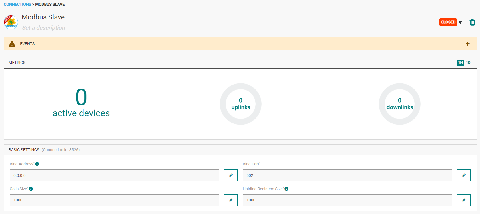
Changing the Settings after Creation
You can change settings parameters such as the destination URL or the Headers after the creation of the MODBUS application.
To do this, proceed as follows:
-
Select the MODBUS application for which you want to change one or several parameters.
-
In the application information dashboard, click on the Edit icon corresponding to the parameter you want to change.
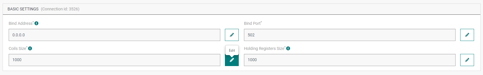
- Enter the new value, and click on the Confirm icon.
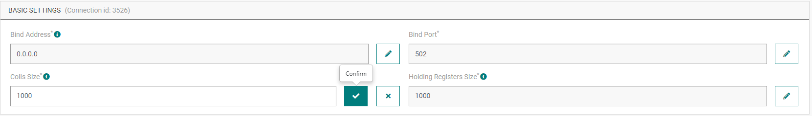
- The Confirmation window displays,
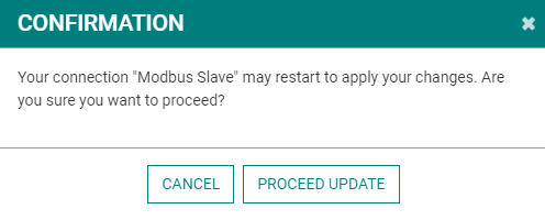
- A notification will inform you that the parameter is updated.
Direct Mapping Rules
This first way is very strict but you can control each address allocation.
Each rule mapped a data value of a device to a particular register of a slaveID.
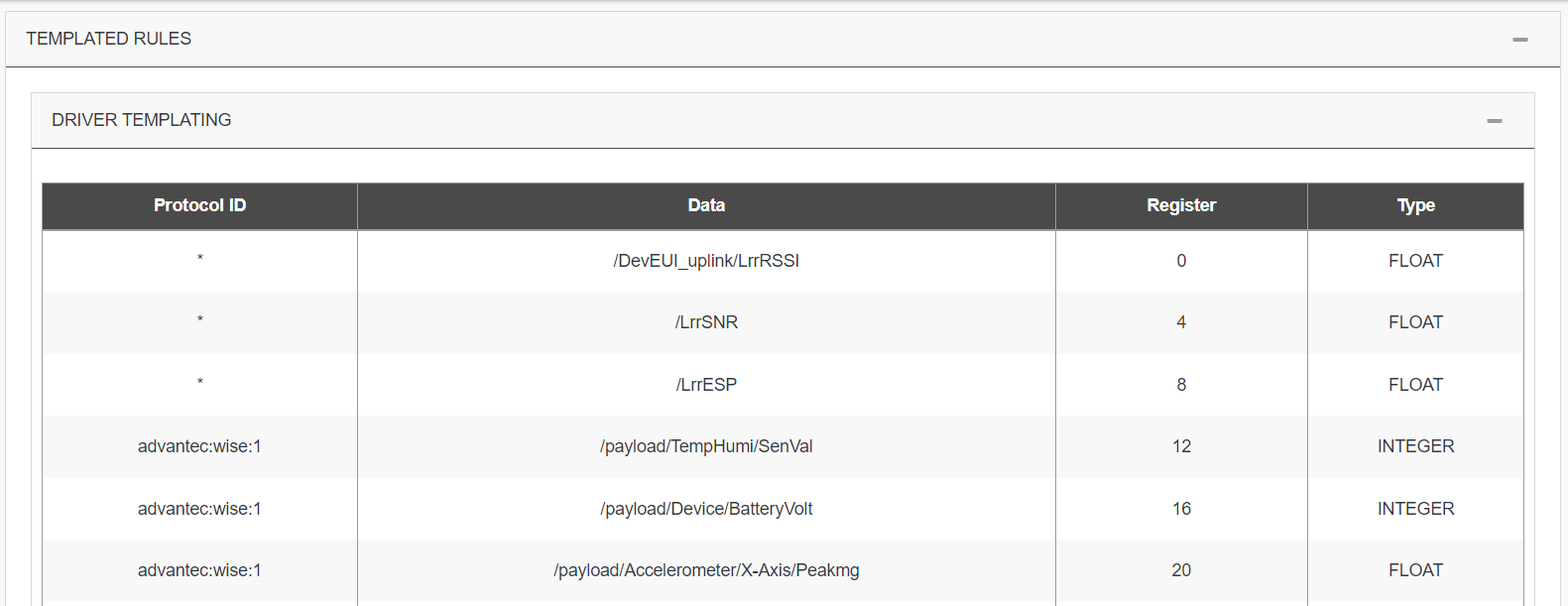
Templated Rules
This second way can be used with the direct mapping rules. It's more dynamic, the mapping is based on driver output.
-
You need do the relation of a datapath available on the output of a specific driver to a register.
-
You need map a device to slaveID and can use also add an offset for using more space area.
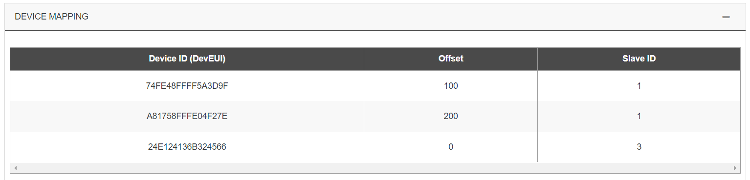
On examples above, if devices 74FE48FFFF5A3D9F and A81758FFFE04F27E are Advantech Wise 1, the part of the registry can contain:
| Device | Data | Register | SlaveID |
|---|---|---|---|
| 74FE48FFFF5A3D9F | /LrrESP | 108 | 1 |
| A81758FFFE04F27E | /LrrESP | 208 | 1 |
| 24E124136B324566 | /LrrESP | 8 | 3 |
| 74FE48FFFF5A3D9F | /payload/Device/BatteryVolt | 116 | 1 |
| A81758FFFE04F27E | /payload/Device/BatteryVolt | 216 | 1 |
Even if 24E124136B324566 is not an Advantech Wise 1, some datas can be extracted if protocol ID used is a star.
Remark on data types
MODBUS coils are registers that hold boolean (true/false) values. So if coilsSize property is set to 1000, this means we can hold 1000 discrete true/false values inside the registry.
Actility MODBUS connector currently supports the following data types which are mapped from an uplink JSON field to one of the data types listed below:
| Data type | Description |
|---|---|
| BOOLEAN | A single true/false value that is written to a MODBUS coil. The address of the coil that the value will be read from or written to must be specified in the mapping rules configuration property. |
| INTEGER UNSIGNED (16BITS) | A 16 bit unsigned INTEGER value that is written to a MODBUS holding register. |
| INTEGER SIGNED (16BITS) | A 16 bit signed INTEGER value that is written to a MODBUS holding register. |
| INTEGER UNSIGNED (32BITS) | A 16 bit unsigned INTEGER value that is written to a MODBUS holding register. |
| INTEGER SIGNED (32BITS) | A 16 bit signed INTEGER value that is written to a MODBUS holding register. |
| FLOAT | A 16 bit half precision floating point value that is written to a MODBUS holding register. |
| DOUBLE | A 32 bit precision floating point value that is written to a MODBUS holding register. |
MODBUS holding registers are 16 bit length registers that can hold arbitrary values. For example, a single MODBUS holding register can hold one of the following values:
- A 16 bit signed int value
- A 16 bit unsigned int value
- A 16 bit half precision float value For storing other data types, we need to use multiple registers. How the data is written and read is completely dependent on the implementation.
Creating a connection with API
To do this, you need to use the Connections group resource:
POST/connectionsto create a new Connection instancePUT/connectionsto update a Connection instanceDELETE/connectionsto delete a Connection instance
We follow the REST-full API pattern, when updating configuration properties for a connection resource. Thus, you must also provide the whole configuration again.
Example for creation of a new connection instance :
POST /connections
{
"connectorId": "actility-modbus-iot",
"name": "Modbus Slave",
"configuration": {
"bindAddress": "0.0.0.0",
"bindPort": 502,
"coilsSize": 1000,
"holdingRegistersSize": 1000,
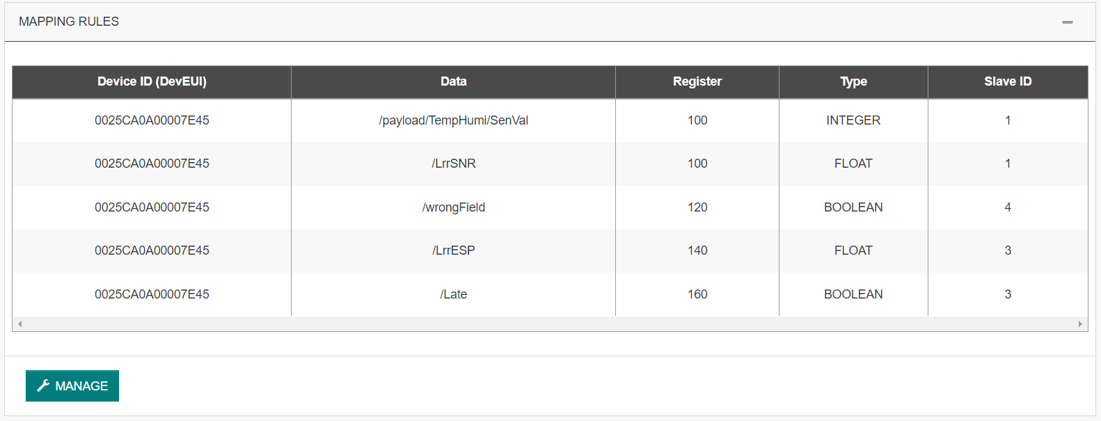
"mappingRules": [
{
"devEUI": "0025CA0A00007E45",
"data": "/payload/TempHumi/SenVal",
"register": 100,
"type": "INTEGER",
"slaveId": 1
},
{
"devEUI": "0025CA0A00007E45",
"data": "/LrrSNR",
"register": 100,
"type": "FLOAT",
"slaveId": 1
},
{
"devEUI": "0025CA0A00007E45",
"data": "/wrongField",
"register": 120,
"type": "BOOLEAN",
"slaveId": 4
},
{
"devEUI": "0025CA0A00007E45",
"data": "/LrrESP",
"register": 140,
"type": "FLOAT",
"slaveId": 3
},
{
"devEUI": "0025CA0A00007E45",
"data": "/Late",
"register": 160,
"type": "BOOLEAN",
"slaveId": 3
}
],
"mappingTemplatedRules": {
"templatingRules": [
{
"data": "/DevEUI_uplink/LrrRSSI",
"protocolId": "*",
"register": 0,
"type": "FLOAT"
},
{
"data": "/LrrSNR",
"protocolId": "*",
"register": 4,
"type": "FLOAT"
},
{
"data": "/LrrESP",
"protocolId": "*",
"register": 8,
"type": "FLOAT"
},
{
"data": "/payload/TempHumi/SenVal",
"protocolId": "advantec:wise:1",
"register": 12,
"type": "INTEGER"
},
{
"data": "/payload/Device/BatteryVolt",
"protocolId": "advantec:wise:1",
"register": 16,
"type": "INTEGER"
},
{
"data": "/payload/Accelerometer/X-Axis/Peakmg",
"protocolId": "advantec:wise:1",
"register": 20,
"type": "FLOAT"
},
{
"data": "/payload/Accelerometer/Y-Axis/Peakmg",
"protocolId": "advantec:wise:1",
"register": 24,
"type": "FLOAT"
},
{
"data": "/payload/Accelerometer/Z-Axis/Peakmg",
"protocolId": "advantec:wise:1",
"register": 28,
"type": "FLOAT"
},
{
"tag": [
"Abeeway",
"nke"
],
"data": "/payload/Accelerometer/Z-Axis/Peakmg",
"register": 30,
"type": "FLOAT"
}
],
"deviceToSlaveIds": [
{
"deviceEUI": "74FE48FFFF5A3D9F",
"offset": 100,
"slaveId": 1
},
{
"deviceEUI": "A81758FFFE04F27E",
"offset": 200,
"slaveId": 1
},
{
"deviceEUI": "24E124136B324566",
"offset": 0,
"slaveId": 3
}
]
}
}
}
The following table lists properties of a connection instance.
| Field | Description |
|---|---|
connectorId | Must be set to actility-modbus-iot. |
bindAddress | The IP address on which the embedded MODBUS slave will bind on in case the server has multiple network interfaces. |
bindPort | The port on which the embedded MODBUS slave will be listening on. Only port range from 502 to 507 are allowed. |
coilsSize | The number of MODBUS coils (coils hold boolean true/false values) in the registry. |
holdingRegistersSize | The number of MODBUS holding registers (each register holds a 16 bit value) in the registry. |
mappingRules | Is an array of rules which describes the mapping between the incoming uplink JSON payload and how it will be represented in the MODBUS registry. |
mappingTemplatedRules/deviceToSlaveIds | Is an array of rules which describes the mapping between a data path of a driver and a base address registry. |
mappingTemplatedRules/templatingRules | Is an array of rules which describes the mapping between a device and a final MODBUS registry. |
All properties are not present in this example. You can check the rest of these properties in the common parameters section.
Limitations
When the coils size or inputRegistersSize properties of the MODBUS connector is changed, the existing MODBUS registry is wiped out and a new MODBUS registry is created. Thus, all the existing values inside the registry will be lost.
Displaying information to know if it worked
- Send the following uplink packet
{
 "DevEUI_uplink": {
   "Time": "2021-10-28T17:04:09.387+00:00",
   "DevEUI": "A30958FFFE05A175",
   "FPort": 5,
   "FCntUp": 69725,
   "ADRbit": 1,
   "MType": 2,
   "FCntDn": 8733,
   "payload_hex": "0100df022904002b0500070e4e",
   "mic_hex": "aadbf8dd",
   "Lrcid": "000000CB",
   "LrrRSSI": -42.0,
   "LrrSNR": 9.25,
   "LrrESP": -42.48772,
   "SpFact": 7,
   "SubBand": "G1",
   "Channel": "LC2",
   "DevLrrCnt": 2,
   "Lrrid": "10000035",
   "Late": 0,
   "Lrrs": {
     "Lrr": [
       {
         "Lrrid": "10000035",
         "Chain": 0,
         "LrrRSSI": -42.0,
         "LrrSNR": 9.25,
         "LrrESP": -42.48772
       },
       {
         "Lrrid": "100001F7",
         "Chain": 0,
         "LrrRSSI": -32.0,
         "LrrSNR": 7.5,
         "LrrESP": -32.710819
       }
     ]
   },
   "CustomerID": "100002164",
   "CustomerData": {
     "alr": {
       "pro": "ELSYS/A",
       "ver": "1"
     }
   },
   "ModelCfg": "1:TWA_100002164.1105.AS",
   "DriverCfg": {
     "mod": {
       "pId": "elsys",
       "mId": "ers",
       "ver": "1"
     },
     "app": {
       "pId": "elsys",
       "mId": "generic",
       "ver": "1"
     }
   },
   "InstantPER": 0.0,
   "MeanPER": 1.1E-5,
   "DevAddr": "0512B338",
   "AckRequested": 0,
   "rawMacCommands": "",
   "TxPower": 2.0,
   "NbTrans": 1,
   "Frequency": 867.3,
   "DynamicClass": "A",
   "payload": {
     "temperature": 19.4,
     "humidity": 46,
     "light": 43,
     "motion": 0,
     "vdd": 3662
   },
   "points": {
     "temperature": {
       "unitId": "Cel",
       "type": "double",
       "record": 19.4
     },
     "humidity": {
       "unitId": "%RH",
       "type": "double",
       "record": 46
     },
     "light": {
       "unitId": "lx",
       "type": "double",
       "record": 43
     },
     "co2Level": {
       "unitId": "ppm",
       "type": "double",
       "record": 43
     },
     "batteryVoltage": {
       "unitId": "mV",
       "type": "double",
       "record": 3662
     },
     "batteryLevel": {
       "unitId": "%",
       "type": "double",
       "record": 101.72
     }
   }
 }
}
-
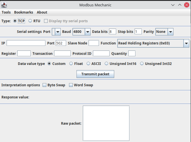
Download and unzip the latest release of Modbus Mechanic.
-
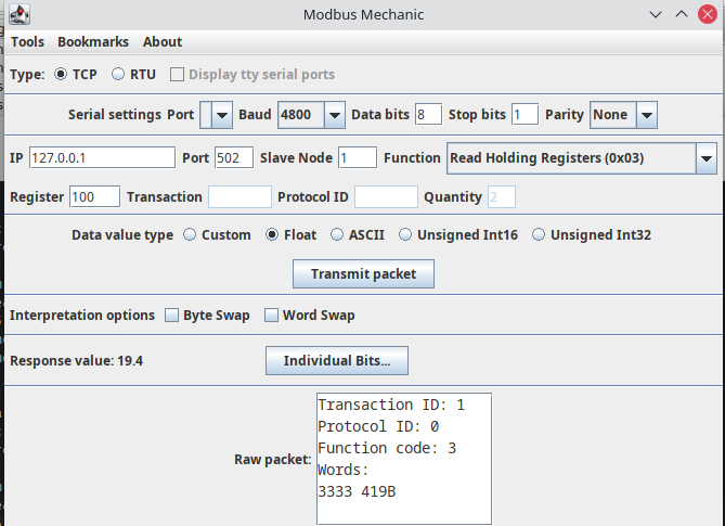
Execute the ModbusMechanic.jar file by double clicking on it inside the extracted ModbusMechanic folder. You should see the GUI shown in the picture below;
-
Fill in the IP and Port values according to your MODBUS connector configuration. Set the SlaveNoe value to 1. Selec the Read Holding Registers (0x03) command from the dropdown.
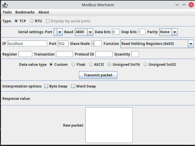
-
Enter the register number as 100 and Data value type as Float. Click on Transmit Packet button. You should see the response value as 19.4
-
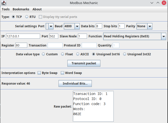
Enter the register number as 80 and Data value type as Unsigned Int16. Click on Transmit Packet button. You should see the response value as 46.
Troubleshooting
As for now, there are no detected bugs or constraints.