Creating a LoRaWAN® device
You must have read-write access to Device Manager. For more information, see Opening a panel and checking your read-write access.
OTAA versus ABP devices
For LoRaWAN® connectivity, you can create OTAA and ABP devices that are manufactured with a different mode of registration and activation on the network:
| Device | Activation | Tips |
|---|---|---|
| Activation By Personalization (ABP) | The configuration of the device is static. | When creating an ABP device, you must have a DevAddr to enter. |
| Over The Air Activation (OTAA) | The configuration of the device is dynamic. | When creating an OTAA device, the DevAddr is not needed because it is generated by the network at every join request of the device. |
Class B devices
You can create LoRaWAN® devices of class A, B and C with Device Manager.
If you want to create an OTAA or ABP class B device, you must use a model and a connectivity plan that both support class B. It will make the manufactured-class B device switch to class B mode after a successful acquisition of the beacon signal.
The device model is created and managed by your operator. For more information, see More about models and manufacturers. The connectivity plan is created by the connectivity supplier and is included in a Vendor offer to be purchased by the Subscriber. For more information, see the Class B support parameter in LoRaWAN® unicast connectivity plan details.
For more information about class B devices, see Viewing general information, activity summary and location of a device.
Creating an OTAA device
You must know the manufacturer and the model of the OTAA device you want to register in Device Manager to connect it to your IoT network. When selected, the model applies the LoRaWAN® version, class and configuration of the device. For more information, see More about models and manufacturers.
You must have the following information ready to be used:
| For a LoRaWAN® 1.0 device | For a LoRaWAN® 1.1 device |
|---|---|
|
|
1 Not required if the LRC (network server) works with an external Join Server configuration. For more information, see ThingPark Wireless Join Server Solution Description. Can be RSA encrypted. 2 If you have subscribed to the Address Manager. | |
Notes
-
The connectivity plan and the AS routing profile are necessary to make the device work. You can associate them by editing the device later as described in Allocating a connectivity plan and Allocating an AS routing profile.
-
If you want a hardware protection of the device's root keys, you must use a connectivity plan and an AS routing profile that both enable HSM protection. For more information, see LoRaWAN® unicast connectivity plan details and Configuring a LoRaWAN® AS routing profile for HSM.
-
In the navigation panel, click Devices to open the Devices panel.
-
In the Add Devices frame of the Devices panel, click Create.
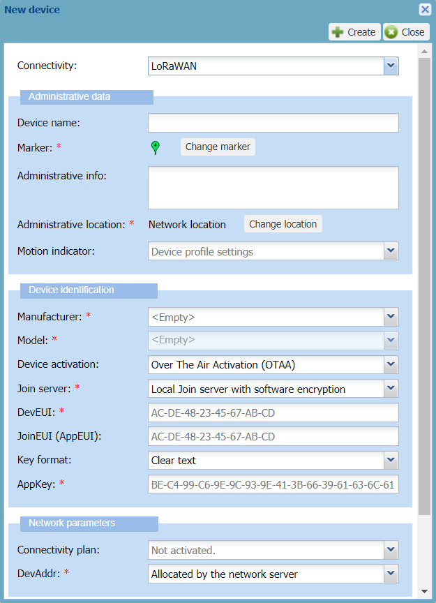
-> By default, the New device dialog box appears with LoRaWAN® 1.1 connectivity and OTAA configuration.
Tips
-
Only the fields marked with an asterisk are required.
-
A tooltip appears when hovering your mouse over a field.
-
An example is given that disappears when entering your data.
-
To help you, type slowly in a box until a blue frame appears. If the frame is red, your data is incorrect.
-
In the Administrative data frame, enter the following information:
-
Device name: Enter a name that helps you identify easily the device on your IoT network.
-
Marker: If you want to change the default device marker, click Change the marker, and apply Changing the device marker from step 3.
-
Administrative info: Type any useful information related to the device. Such information is displayed in alarm notification emails. For more information, see Setting alarm notification emails.
-
Administrative location: By default, the network location is set for the device. If you want to set the manual location, click Change location, and apply Manual location: locating a device or editing its location from step 3.
-
Motion indicator: To allow the network server to use the best base station to send downlinks, replace Device profile settings by the motion indicator that best applies to your device during operation. Note If your device is always static, select Near static. If your device can change location during operation, do not select Near static.
-
-
In the Device identification frame, apply the configuration corresponding to the device you have as follows:
-
In the Manufacturer list, select the manufacturer of the device. If it is not in the list, contact your operator.
-> It populates the Model list with the device models of the manufacturer.
-
In the Model list, select the model of the device. If defined by your operator, the model name is followed by the supported ISM bands. If the model is not in the list, contact your operator.
-> The dialog box is updated with the model configuration. If the model supports LoRaWAN® 1.1, the dialog box is updated with related parameters.
-
In the Device activation list: Over The Air Activation (OTAA) must be selected
-
-
In the Join server list, select the join server mode on which you want the OTAA device to do its join procedure:
-
If you want to use a joint server that is local to the network server with software protection of the device's root keys, select Local Joint server with software encryption.
-
If you want to use a joint server that is local to the network server with hardware protection of the device's root keys, select Local Joint server with HSM protection, then from the HSM group list that appears, select the HSM group you want to use.
-
If you want to use a joint server that is external to the network server, select External joint server and go to step 9.
-
-
According to the LoRaWAN® version supported by the model you have selected, enter the device information in the boxes that are displayed:
-
DevEUI: Globally unique identifier of the device which is written on it. It is composed of 16 hexadecimal digits (0 to 9, and A to F).
-
JoinEUI (AppEUI): JoinEUI for LoRaWAN® 1.1 (AppEUI for LoRaWAN® 1.0). Global application identifier that uniquely identifies the application provider of the device. It is composed of 16 hexadecimal digits (0 to 9, and A to F). It is mandatory only when using an external join server.
-
-
If you are using a local join server with software encryption and you want to enter the AppKey in clear text:
-
Select Clear text from the Key format list.
-
Enter the following information in the boxes that appears:
-
NwkKey: Only displayed if the model you have selected supports LoRaWAN® 1.1. The Network Key is anAES-128 key that encrypts the device's communication with the network. It is composed of 32hexadecimal digits (0 to 9, and A to F).
-
AppKey: The Application Key is an AES-128 key assigned by the application owner to the device to encrypt the join communication.
-
-
-
If you are using a local join server with software encryption and you want to enter an RSA encrypted AppKey, or if you are using a local join server with hardware protection, apply the following:
-
From the Key format list, select RSA encrypted.
-> The RSA encrypted AppKeybox appears.
-> The RSA encrypted NwkKey box also appears if the model you have selected supports LoRaWAN® 1.1.
-
Click Download RSA Public Key to download it in X.509 SubjectPublicKeyInfo /OpenSSL PEM format.
-
Using for instance an OpenSSL command in a shell terminal, encrypts the AppKey (and the NwkKey if using LoRaWAN® 1.1) with the RSA public key (PKCS#1 v1.5 padding) as follows:
openssl rsautl –encrypt –in appKey.bin –inkey TWK1.pem –pubin –pkcs –out encryptedAppKey.bin
openssl rsautl –encrypt –in nwkKey.bin –inkey TWK1.pem –pubin –pkcs –out encryptedNwkKey.bin
Where:
-
appKey.binis the AppKey in binary format. For example, you can setappKey.binby executing the following commands:-
echo
{MY_APPKEY_IN_HEXA}>appKey.hex -
cat
appKey.hex| xxd --r --p >appKey.bin
-
-
nwkKey.binis the NwkKey in binary format -
TWK1.pemis the RSA Public Key in X.509 SubjectPublicKeyInfo/OpenSSL PEM format -
encryptedAppKey.binis the RSA encrypted AppKey in binary format -
encryptedNwkKey.binis the RSA encrypted NwkKey in binary format.
-
-
Do one of the following:
-
If you want to enter the RSA encrypted AppKey uploading the binary file resulting from the encryption:
-
Save
encryptedAppKey.binon your workstation. -
Click Browse... next to the RSA encrypted AppKey box.
-
Repeat for the RSA encrypted NwkKey if using LoRaWAN® 1.1.
-
-
Otherwise, if you want to enter the RSA encrypted AppKey as a base64 string:
-
Using for instance a Linux command in a shell terminal, encode
encryptedAppKey.binin base64 as follows:cat encryptedAppKey.bin | base64 -
Copy-paste the result in the RSA encrypted AppKey box.
-
Repeat for the RSA encrypted NwkKey if using LoRaWAN® 1.1.
-
-
-
-
If the Verification codebox if displayed, enter the verification code associated with the DevEUI and provided by your operator. This box is displayed if you have subscribed to the Address Manager.
-
In the Network parameters frame, enter the following information:
-
In the Connectivity plan list:
The number in parenthesis indicates the remaining devices available in the connectivity plan. For more information about connectivity plans, see Viewing connectivity plans.
-
If you want to create a class B device, select a connectivity plan that supports class B. If not, the device will work as a class A device.
-
If you are using a local join server with hardware protection, select a connectivity plan enabling HSM protection.
-
-
In the DevAddr list:
By default, Allocated by the network server is selected. This is the default behavior of the OTAA device having its DevAddr generated by the join procedure.
- If you want to use a specific DevAddr for the device, the device will not have an OTAA behavior anymore. In that case, select Manual configuration (advanced mode), then in the Manual DevAddr box enter the DevAddr you want with 8 hexadecimal digits (0 to 9, and A to F).
-
-
In the Application layer handling frame, enter the following information:
-
In the Application server routing profile list, select an AS routing profile to route the device packets towards one or more applications servers.
-
If you are using a local join server with hardware protection, select an AS routing profile with HSM activated.
-
ImportantYou can only use an AS routing profile that does not contain more destinations, summing up all types of application servers in it, than defined in the connectivity plan associated with the device. For more information, see Maximum allowed Application Servers in LoRaWAN® unicast connectivity plan details.
-
If there is no AS routing profile in the list, you will associate it later by opening the device's Network panel after you have created a LoRaWAN® AS routing profile. For more information, see Managing AS routing profiles and Managing the AS routing profile of a device.
-
-
If supported by the connectivity plan you have selected, the ThingPark X configuration area is displayed. If you want to set a specific ThingPark X configuration for this device, add a ThingPark X driver configuration like this:
-
Click Add.
-
Click the row that appears, then delete the mask to enter the ThingPark X driver configuration provided by your operator.
-
Enter a port number. It can be a range of ports, for instance 1-20. Note* means all ports.
-
-
-
Click Create.
-> If the process takes time, a message tells you that you will receive an email when finished.
-> The device is displayed in the device list.
Creating an ABP device
You must know the manufacturer and the model of the ABP device you want to register in Device Manager to connect it to your IoT network. When selected, the model applies the LoRaWAN® version, class and configuration of the device. For more information, see More about models and manufacturers.
You must have the following information ready to be used:
| For a LoRaWAN® 1.0 device | For a LoRaWAN® 1.1 device |
|---|---|
| Manufacturer Model DevEUI DevAddr NwkSKey AppSKey1 Verification code2 | Manufacturer Model DevEUI DevAddr FNwkSIntKey SNwkSIntKey NwkSEncKey AppSKey1 (optional) Verification code2 (optional) |
| 1 Allows the Wireless Logger to display the packet payload in decoded form and parse it if the syntax is supported. For more information, see More about the AppSKey for ABP devices | |
| 2 If you have subscribed to the Address Manager. |
Note: The connectivity plan and the AS routing profile are necessary to make the device work. You can associate them by editing the device later as described in Allocating a connectivity plan and Allocating an AS routingprofile.
-
In the navigation panel, click Devices to open the Devices panel.
-
In the Add Devices frame, click Create.
-> By default, the New device dialog box appears with LoRaWAN® 1.0 connectivity and OTAA configuration.
-
In the Administrative data frame, enter the following information:
-
Device name: Enter a name that helps you identify easily the device on your IoT network.
-
Marker: If you want to change the default device marker, click Change the marker, and apply Changing the device marker from step 3.
-
Administrative info: Type any useful information related to the device. Such information is displayed in alarm notification emails. For more information, see Setting alarm notification emails.
-
Administrative location: By default, the network location is set for the device. If you want to set the manual location, click Change location, and apply Manual location: locating a device or editing its location from step 3.
-
Motion indicator: To allow the network server to use the best base station to send downlinks, replace Device profile settings by the motion indicator that best applies to your device during operation. Note If your device is always static, select Near static. If your device can change location during operation, do not select Near static.
-
-
In the Device identification frame, apply the configuration corresponding to the device you have as follows:
-
In the Manufacturer list, select the manufacturer of the device. If it is not in the list, contact your operator.
-> It populates the Model list with the device's models of the manufacturer.
-
In the Model list, select the model of the device. If defined by your operator, the model name is followed by the supported ISM bands. If the model is not in the list, contact your operator.
-> The dialog box is updated with the model configuration. If the model supports LoRaWAN® 1.1, the dialog box is updated with related parameters.
-
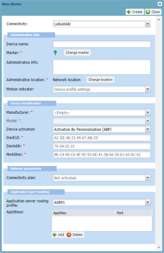
In the Device activation list, select Activation By Personalization (ABP).
-> The dialog box is updated with ABP configuration.
-
Tips
-
Only the fields marked with an asterisk are required.
-
A tooltip appears when hovering your mouse over a field.
-
An example is given that disappears when entering your data.
-
To help you, type slowly in a box until a blue frame appears. If the frame is red, your data is incorrect.
-
According to the LoRaWAN® version supported by the model you have selected, enter the device information in the boxes that are displayed:
-
DevEUI: Globally unique identifier of the device which is written on it. It is composed of 16 hexadecimal digits (0 to 9, and A to F).
-
DevAddr: Device address on the network. Composed of 8 hexadecimal digits (0 to 9, and A to F), it identifies the device on the current network.
-
NwkSKey: Applies to LoRaWAN® 1.0. TheNetwork Session Key is an AES-128 key composed of 32hexadecimal digits (0 to 9, and A to F).
-
FNwkSIntKey: Applies to LoRaWAN® 1.1. TheForwarding Network Session Integrity Keyis composed of 32hexadecimal digits (0 to 9, and A to F).
-
SNwkSIntKey: Applies to LoRaWAN® 1.1. TheServing Network Session Integrity Key. is composed of 32hexadecimal digits (0 to 9, and A to F).
-
NwkSEncKey: Applies to LoRaWAN® 1.1. TheNetwork Session Encryption Keyis composed of 32hexadecimal digits (0 to 9, and A to F).
-
Verification code: Only displayed if you have subscribed to the Address Manager. Enter the verification code associated with the DevAddr/DevEUI pair and provided by your operator.
-
-
In the Network parameters frame, select a Connectivity plan from the list:
The number in parenthesis indicates the remaining devices available in the connectivity plan. For more information about connectivity plans, see Viewing connectivity plans.
- If you want to create a class B device, select a connectivity plan that supports class B. If not, the device will work as a class A device.
-
In the Application layer handling frame, enter the following information:
-
In the Application server routing profile list, select an AS routing profile to route the device packets towards one or more applications servers:
-
ImportantYou can only use an AS routing profile that does not contain more destinations, summing up all types of application servers in it, than defined in the connectivity plan associated with the device. For more information, see Maximum allowed Application Servers in LoRaWAN® unicast connectivity plan details.
-
If there is no AS routing profile in the list, you must associate it later by opening the device's Network panel after you have created a LoRaWAN® AS routing profile. For more information, see Managing AS routing profiles and Managing the AS routing profile of a device.
-
-
If you want the payloads to be encrypted, you can enter one distinct AppSKey for each LoRaWAN® ports used by your device. You can also use a unique AppSKey for a range of ports or all LoRaWAN® ports. In the AppSKeys area:
-
Click Add.
-
Click the row that appears, then delete the mask to enter the AppSKey (128-bit hexadecimal key, 32 hexadecimal digits from 1 to 9 and A to F).
-
Enter a Port number, a range of ports (example: 1-20), or all ports using*.
-
Repeat as necessary to add more AppSkeys.
-
-
If supported by the connectivity plan you have selected, the ThingPark X configuration area is displayed. If you want to set a specific ThingPark X configuration for this device, add a ThingPark X driver configuration like this:
-
Click Add.
-
Click the row, then delete the mask to enter the ThingPark X driver configuration provided by your operator.
-
Enter a port number. It can be a range of ports, for instance 1-20, or all ports using *.
-
Repeat as necessary to add more ThingPark X driver configurations.
-
-
-
Click Create.
-> If the process takes time, a message tells you that you will receive an email when finished.
-> The device is displayed in the device list.
More about the AppSKey for ABP devices
You can use an application session key when creating an ABP device if you want the device payloads to be encrypted.
The optional 128-bit AppSKey allows the LRC in the network server to encrypt and decrypt the payload of the packets. It must be shared with the application servers.
-
If you do not provision AppSKey: ThingPark Wireless forwards the payload in encrypted form to the application server(s) and has no access to the payload clear-form content. Consequently, network tools like Wireless Logger cannot decode the payload and will display it in encrypted form.
-
If you provision one or more AppSKeys: The LRC decodes the payload before forwarding it to the application server(s). Consequently, the Wireless Logger can display the packet payload in decoded form and parse it if the payload syntax is supported.
You can use a unique AppSKey for a range of ports or all LoRaWAN® ports used by your device, or allocate one distinct AppSKey for each port. For more information, see Creating an ABP device.