Downlink LoRaWAN® multicast packets
This topic describes reference information about downlink LoRaWAN® multicast packets.
Multicast
Multicast allows a group of devices to receive the same downlink packet at the same time by transmitting it only once by the base station. It offers significant downlink capacity gain and optimizes the usage of the radio resources.
A multicast group is composed of LoRaWAN® devices implementing:
-
A regular unicast ABP or OTAA device, associated with a first set of {DevEUI, DevAddr, NwkSKey, AppSKey} for ABP and {DevEUI, AppKey} for OTAA
-
A virtual ABP device of Class B or C, associated with another set of {DevEUI, DevAddr, NwkSKey, AppSKey} pre-shared by all members of the multicast group.
To learn more about multicast feature, see Organizing your network in multicast groups.
Downlink multicast packets
In Wireless Logger, multicast downlink packets are represented by:
 in case of transmission success
by the LRR base station.
in case of transmission success
by the LRR base station. in case of radio transmission
failure The detailed delivery failure cause is shown in the expandable
panel. To learn more, see Multicast transmission failure causes.
in case of radio transmission
failure The detailed delivery failure cause is shown in the expandable
panel. To learn more, see Multicast transmission failure causes.
Additionally, the class of the multicast group is indicated in the expandable panel, among other metadata described in Multicast downlink metadata.
The same downlink multicast packet may be displayed several times in Wireless Logger.
-
This represents a multicast packet sent over several base stations associated with the multicast group. In Wireless Logger, the downlink transmission towards each individual base station is displayed separately.
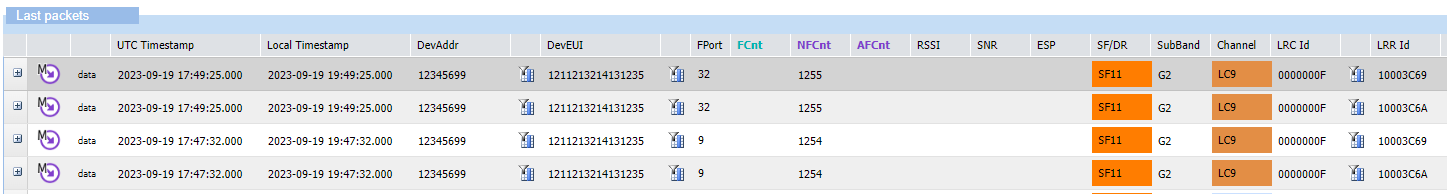
Example The downlink multicast packets with frame counters 1254 and 1255 were transmitted by the network on two different LRR base stations.
-
This may also happen when the initial transmission of the downlink multicast packet was not successful on all the base stations involved in the multicast session. In this case, the LRC network server reattempts to transmit again the downlink packet via the base station that reported transmission failure on the previous attempt. The maximum number of LRC attempts is configured in the multicast connectivity plan associated with the subscriber's multicast group. By default, it is set to 3 transmissions.
Multicast downlinks metadata
See Downlink metadata columns and Downlink expandable panel.
Multicast summary report
For each downlink multicast packet, Wireless Logger displays a multicast summary report. The purpose of this report is to give the effective radio frequency transmission status of the downlink multicast packet.
Effective radio frequency transmission only ensures that the downlink packet has effectively been transmitted by an LRR base station. It does not guarantee that the device has received it.
The final multicast summary report is illustrated by:
- the
 icon if the transmission
was successful over at least 80% of the LRR base stations.
icon if the transmission
was successful over at least 80% of the LRR base stations. - the
 icon if the transmission
success ratio is between 30 and 80%.
icon if the transmission
success ratio is between 30 and 80%. - the
 icon if the transmission
success ratio is lower than 30%.
icon if the transmission
success ratio is lower than 30%.
The following screenshot shows an example for the two multicast packets represented in the earlier example of this page. In this example, the multicast transmission was successful on the two base stations participating to the multicast session.

In case of transmission failure on one or several LRR base stations, either after the first transmission attempt by the LRC or after the maximum number of transmission attempts, the multicast summary report provides the distribution of LRR failure delivery causes.
Transmission status shows multicast downlink transmission status:
| Transmission status | Explanation |
|---|---|
| PARTIAL | Some LRRs failed to transmit the downlink packet. Another attempt will be made to transmit the packet to theses LRRs. |
| SUCCESS | All LRRs successfully transmitted the downlink packet. |
| ABORTED | Some LRRs failed to transmit the downlink. No more attempt will be made to transmit the packet to theses LRRs (maximum number of attempts already reached). |
Multicast transmission failure causes
The following table lists the various causes and their explanation:
| Cause value | Category name |
|---|---|
| Ax | Transmission slot busy
|
Bx (Multicast class B only) | Received too late for ping slot
|
| Dx | Duty cycle or gateway constraint
|
Ex (Multicast class C only) | Frame expired before transmitting
|
Example In the following multicast summary report, we can see that a transmission slot has been twice busy (A3) while the failure causes of the gateway constraint have occurred 7 times (D0) and 3 times (DC).
