LoRaWAN® traffic overview
This topic describes LoRaWAN® summary information displayed in the Last packets list. For more information, see Viewing the traffic.
LoRaWAN® packets
Unicast packets
| Symbol | Name | Description |
|---|---|---|
| Unicast uplink | Transmission success to all application servers | |
| Failed unicast uplink | Transmission failure to at least one application | |
| Unicast downlink | Radio transmission success | |
| Failed unicast downlink | Radio transmission failure | |
| Unicast downlinks for a repeated uplink | Downlinks generated for a repeated uplink |
Multicast
| Symbol | Name | Description |
|---|---|---|
| Multicast downlink | Multicast downlink | |
| Failed multicast downlink | Radio transmission failure |
Forwarding passive roaming
The network server acts as a forwarding network server. Applies to Wireless Logger attached to a network partner account or to a subscriber account with a Network Manager subscription.
| Symbol | Name | Description |
|---|---|---|
| Passive roaming uplink (fNS) | Uplink transmitted to the serving network server of the foreign device. | |
| Passive roaming downlink (fNS) | Downlink sent by the serving network server of the foreign device roaming in on my network. The downlink was successfully radio-transmitted by one of my base stations. | |
| Failed passive roaming downlink (fNS) | Downlink sent by the serving network server of the foreign device roaming in on my network. The donwnlink was unsuccessfully radio-transmitted by one of my base stations |
Serving passive roaming
The network server acts as a forwarding network server. Applies to Wireless Logger attached to a network partner account or to a subscriber account with a Network Manager subscription.
| Symbol | Name | Description |
|---|---|---|
| Passive roaming uplink (sNS) | Transmission success to all application servers of an uplink of one of my devices roaming out on a foreign network and passing through a foreign base station. | |
| Failed passive roaming uplink (sNS) | Transmission failure to at least one application server of an uplink of one of my devices roaming out on a foreign network and passing through a foreign base station. | |
| Passive roaming downlink (sNS) | Radio transmission success of a downlink of one of my devices roaming out on a foreign network and passing through a foreign base station. | |
| Failed passive roaming downlink (sNS) | Radio transmission failure of a downlink of one of my devices roaming out on a foreign network and passing through a foreign base station. |
LoRaWAN® reports
Unicast
| Symbol | Name | Description |
|---|---|---|
| Location report | ||
| Device reset report | Only available if Wireless Logger is attached to a subscriber account |
Multicast
| Symbol | Name |
|---|---|
| Multicast summary report |
Radio color codes
Wireless Logger displays a range of colors for radio parameters that are subject to limited values in the columns of the Last packets list. For more information about LoRaWAN® radio parameters, see LoRaWAN® radio statistics.
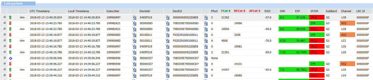
Signal-to-Noise Ratio and Estimated Signal Power
In the SNR and ESP columns, Signal-to-Noise Ratio and Estimated Signal Power parameters apply the following rules:
| Parameter | Green | Orange | Red |
|---|---|---|---|
| Signal-to-Noise Ratio (SNR) | value ≥ - 8 dB | - 13 dB ≤ value ≤ - 8 dB | value < - 13 dB |
| Estimated Signal Power (ESP) | value ≥ - 100 dBm | - 110 dBm ≤ value ≤ - 100 dBm | value < - 110 dBm |
Spreading Factor or Data Rate
In the SF/DR column, if a Spreading Factor or a Data Rate displays a value, the following rules apply:
| Spreading Factor or Data Rate value | Displayed color |
|---|---|
| Value ≤ SF10 | Green |
| Value is SF11 | Orange |
| Value is SF12 | Red |
| Value is FDRx | Cyan |
RX2
If the value displayed in the Channel column is RX2, it is displayed in orange.
LoRaWAN® radio statistics
This topic provides information about the calculation of LoRaWAN® radio parameters. They apply to uplinks.
Estimated Signal Power (ESP)
Estimates the real received signal strength of a desired signal considering the impact of background noise.
Being the received signal strength of the useful signal, it represents the S component in the Signal-to-Noise Ratio (SNR) formula. Therefore, ESP can be computed as follows:
- ESP = Tx EIRP – Path Loss + Rx antenna gain
- ESP = RSSI – 10*LOG( 1 + 10(-SNR/10) )
Allows assessing how good the received signal is compared to the minimum sensitivity level of the receiver. It is expressed in dBm and always has negative values.
Received Signal Strength Indicator (RSSI)
Determines the total received signal strength within a channel bandwidth summing up the useful signal (S), the interference (I), and the background noise (N).
Expressed in dBm, RSSI is the sum S + I + N.
Signal-to-Noise Ratio (SNR)
Determines the quality of the reception through the ratio between the received signal strength of the useful signal (S), and the signal strength of the interference (I) added to the one of the background noise (N).
It is computed like this: SNR = S/(I+N). It is expressed in dB.
The higher the SNR (for instance positive SNR as opposed to negative SNR), the better the reception quality.