Downlink LoRaWAN® multicast packets
This topic describes reference information about downlink LoRaWAN® multicast packets.
Multicast
Multicast allows a group of devices to receive the same downlink packet at the same time by transmitting it only once by the base station. It offers significant downlink capacity gain and optimizes the usage of the radio resources.
A multicast group is composed of LoRaWAN® devices implementing:
-
A regular unicast ABP or OTAA device, associated with a first set of
{DevEUI, DevAddr, NwkSKey, AppSKey}for ABP and{DevEUI, AppKey}for OTAA -
A virtual ABP device of Class B or C, associated with another set of
{DevEUI, DevAddr, NwkSKey, AppSKey}pre-shared by all members of the multicast group.
Multicast downlinks
Multicast downlink packets are represented with a special multicast
flag ![]() .
.
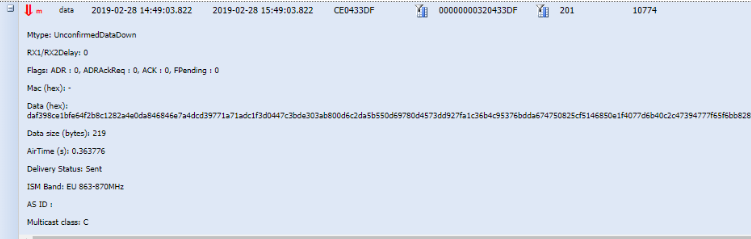
In the expandable panel, the class of the multicast group is indicated:
Multicast class C.
Reattempts of multicast downlink transmission to base stations failed
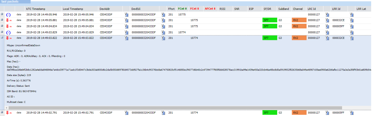
The same downlink multicast packet may be transmitted displayed several times in Wireless Logger. This happens when the initial transmission of the downlink multicast packet was not successful on all the base stations involved in the multicast session. In this case, the LRC reattempts to transmit again the downlink packet to via the base station that reported transmission failure on the previous attempt. The maximum number of LRC attempts is configured in the multicast connectivity plan associated with the subscriber's multicast group. By default, it is set to 3 transmissions.
Example This downlink multicast packet has been transmitted more
than once by the LRC. Notice the downlink frame counters 10774 and
10775:
Multicast downlinks metadata
See Downlink metadata columns and Downlink expandable panel.
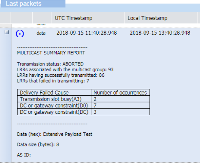
Multicast summary report
For each downlink multicast packet, Wireless Logger displays a multicast summary report. The purpose of this report is to give the effective radio frequency transmission status of the downlink multicast packet.
Note Effective radio frequency transmission only ensures that the downlink packet has effectively been transmitted by an LRR base station. It does not guarantee that the device has received it.
An example of multicast summary report is provided below, it is
represented by the ![]() symbol.
symbol.

In this example, the multicast transmission was successful on the two base stations participating to the multicast session.
In case of transmission failure on one or several LRR base stations, either after the first transmission attempt by the LRC or after the maximum number of transmission attempts, the multicast summary report provides the distribution of LRR failure delivery causes.
Transmission status shows multicast downlink transmission status:
| Transmission status | Explanation |
|---|---|
| PARTIAL | Some LRRs failed to transmit the downlink packet. Another attempt will be made to transmit the packet to theses LRRs. |
| SUCCESS | All LRRs successfully transmitted the downlink packet. |
| ABORTED | Some LRRs failed to transmit the downlink. No more attempt will be made to transmit the packet to theses LRRs (maximum number of attempts already reached). |
| Cause value | Category name |
|---|---|
| Ax | Transmission slot busy - (A0) Radio stopped - (A1) Downlink radio stopped - (A2) Ping slot not available (Class B multicast only) - (A3) Radio busy - (A4) Listen before talk - (A5) Radio board error |
| Bx | Received too late for ping slot - (B0) Too late for ping slot |
| Dx | Duty cycle or gateway constraint - (D0) Duty cycle constraint detected by LRR - (DA) Duty cycle constraint detected by LRC - (DB) Max dwell time constraint detected by the LRC - (DC) No GPS-synchronized LRR detected by the LRC (Class B multicast only) - (DD) No LRR connected detected by the LRC - (DF) Wrong NetID |
| Ex | Frame expired before transmitting - (E0) Max delay for Class C - 60 seconds |
Example In the following multicast summary report, we can see that a transmission slot has been twice busy (A3) while the failure causes of the gateway constraint have occurred 7 times (D0) and 3 times (DC).