Base station (BS) attributes
In ThingPark's user interface, editable fields are displayed with grey background.
General attributes
The following table describes the main attributes associated with base stations in ThingPark.
| Attribute | Definition |
|---|---|
| Name | Friendly name of your base station. - It is given during the initial declaration of the base station on ThingPark, but can be changed any time from the base station's detailed dashboard. - You may search base stations by their name on ThingPark's user interface. - The base station name is reported to third party applications in the LoRaWAN packet metadata, alongside the LRR-ID. |
| LRR-UUID | Universally-unique ThingPark identifier of your base station, in the form of <LRR-OUI>-<LRR-GID>:- <LRR-OUI> is the IEEE OUI (Organizationally Unique Identifier) of the base station manufacturer, it consists of 6 hexadecimal characters. For BS using Semtech's Basics Station packet forwarder, the LRR-OUI is 0016C0. - <LRR-GID> is the base station’s unique identifier relatively to the manufacturer. Allowed characters are [0-9][a-z]-_, max 256 characters. For BS using Semtech's Basics Station packet forwarder, the LRR-GID is the gateway-ID, often built based on a hardware reference like the MAC address. The LRR-UUID is set by the base station manager during the provisioning step (see Adding base stations to ThingPark), it cannot be changed later on. |
| LRR-ID | A short (32 bits) identifier of the base station, allocated by the ThingPark system at the end of the base station provisioning step. - Unlike LRR-UUID, LRR-ID is not globally-unique but is unique within each ThingPark platform. - The LRR-ID of each base station remains unchanged until the BS is deleted from the system, hence it is the main identifier throughout the BS lifetime. |
| Manufacturer | The BS manufacturer set by the base station manager during its declaration in the system. - If the manufacturer is unknown, it may be set to Generic. This is typically the case for base stations using Semtech's Basics Station packet forwarder in absence of a branded ThingPark profile. To learn more about which manufacturers have branded ThingPark profiles, see Supported brands of base stations. - Once the base station is added to the system, its manufacturer cannot be changed later on. |
| Model | The BS model set by the base station manager during its declaration in the system. - Thanks to ThingPark's base station catalog, each model is implicitly associated with a set of technical attributes such as the maximum number of antennas supported by the hardware, the packet forwarder type, etc. - For base stations using Semtech's Basics Station packet forwarder, if there is no branded ThingPark profile, the manufacturer must be set to Generic and the model set to Basics Station packet forwarder. - Once the base station is added to the system, its model cannot be changed later on. |
| Packet forwarder | Type of packet forwarder used by the base station to connect to ThingPark, among the following options: - LRR (Long Range Relay): in this case, the field Packet Forwarder displayed in the base station's detailed page shows LRR XXX where XXX corresponds to the LRR version. Note Clicking the - Basics Station. |
| Software version | LRR software version used by the base station. This field is empty for BS using Basics Station packet forwarder. |
| Software restart | Timestamp of the last restart of the LRR software. This information is not relevant if the BS has never connected to the ThingPark core network. This field is empty for BS using Basics Station packet forwarder. |
| RF Region | The LoRaWAN® Regional Parameters document defines several RF profiles depending on the regional RF regulatory context. For each ISM Band, these regional parameters are grouped into RF Regions which determine the radio frequency allocation plan for devices and base stations, together with a set of radio parameters used by the LoRaWAN® MAC layer. For more information about the RF Regions supported by ThingPark's catalog, see RF Regions. Only RF Regions matching the ISM Bands associated with your deployment are proposed by the user interface. Note Do not assign an RF Region exceeding the maximum number of channels supported by your base station. For instance, if your base station supports 8 channels, do not allocate an RF Region with 16 or 64 channels. |
| Tags | Each base station may be associated with one or several tags. Tags may serve various purposes: - Administrative tags, to easily group objects and filter them accordingly. - Multicast tags, to allocate base stations to multicast groups. Multicast type of tags allow grouping all the base stations contributing to the transmission of downlink multicast packets of a multicast group. To learn more about multicast, see multicast groups. |
| Domains | If the segregation based on domains has been enabled by an administrator, the Domains attribute contains the list of domains associated with the BS. If your user account has domain restrictions, the domains you associate with your BS must match your domain restrictions without any domain prefix (only full domains can be assigned to resources). See About domains for more details. |
| RF antennas in use | Number of RF antennas currently used by the base station and physically plugged to it. Note When adding a new base station on ThingPark, this parameter is set by default to the maximum number of RF antennas supported by the underlying BS model, but it can be changed at any time by the BS manager. |
| Certificate | X.509 certificate specific to each base station to secure its connection to the core network either in IPSec or TLS mode. - This certificate is generated by ThingPark's Public Key Infrastructure (namely the Key Installer) and can be downloaded only once by the BS. - Each certificate is associated with an expiration date, that is displayed in the Certificate column of the base station list, as well as in the Security widget under the Advanced tab of the base station's detailed page. Possible values of this attribute are: - Expired: The generation of the BS certificate is enabled but the certificate has already expired. - Expiration in duration: The generation of the BS certificate is enabled and the certificate is still valid.- Not generated: The generation of the BS certificate is disabled by the BS manager. - Retrieving information: The BS has an LRR-UUID, but the status of its certificate is not yet available in the list. Certificates are automatically renewed by the system and downloaded by the BS few days (6 days by default) before they expire (true for LRR versions 2.4.73 onwards). - If, for any reason, the BS needs to re-download its X.509 certificate, the base station manager must manually regenerate it from the user interface, under the Advanced tab of the base station's detailed page. - Regenerating the BS certificate automatically revokes the current certificate to issue a new one. This action could be used in case the current certificate has been compromised. |
| Public Key | For SaaS deployments, base stations using LRR packet forwarder rely on a pair of public and private keys to authenticate with ThingPark's PKI server (also known as the Key Installer). - The key pair is generated by the LRR through the SUPLOG interface, as described in Generating and retrieving the base station’s Public Key. - Setting a wrong Public Key in ThingPark shall prevent the base station from downloading its X.509 security certificate, hence it cannot connect to the network server. - The Public Key authentication is not supported by Basics Station packet forwarder. Additionally, in the current release, the use of public key is not supported in self-hosted ThingPark Enterprise deployments. |
| Location mode | Technique used to locate the base station: - Onboard Global Navigation Satellite System (GNSS) position: the location is automatically reported by a GPS receiver embedded in the base station. This mode is not supported for base stations using Semtech's Basics Station packet forwarder. - Manual: the base station location (latitude and longitude) is manually set by the base station manager. Manual location can be set using one of the following options: - Either via the Search box on the top of the map, - or by directly placing the marker on the map, - or by setting the latitude and longitude in text input below the map. The compass button allows switching between decimal and degree/minute/second formats. If the base station supports LRR software, has a GPS receiver and can receive a stable GPS signal, the "Onboard GNSS position" mode should be used. Otherwise, the "Manual" mode should be used. |
| RF coverage type | This attribute specifies if the BS provides permanent RF coverage or it only offers temporary coverage for recovery purposes. - Permanent (default setting): the BS provides permanent RF coverage to surrounding devices. Accordingly, the uplink packets received through this BS are counted in ADR decisions. Additionally, this BS may be used to route downlink packets for all device classes A/B/C. - Temporary and mobile: the base station does not have a fixed location, it provides temporary RF coverage to surrounding devices. This is typically used for the walk-by or drive-by use cases. Accordingly, if the same uplink packet is received through both permanent and temporary base stations, the reception through the temporary BS does not impact ADR decisions and this temporary BS is not eligible for routing of DL traffic. Otherwise, if the uplink packet is received only through the temporary BS, the device is assumed to be out-of-coverage of the permanent base stations; hence, the network triggers the RF recovery mode for this device, to boost its SF/TxPower and number of repetitions. This BS may be used to route downlink packets for class A devices only, since there is no guarantee that this moving BS will remain within the device's vicinity in class B/C modes. - Temporary and stationary: the base station has a static location for a period of several days, up to a few weeks, but it does not provide permanent RF coverage. This is typically the case of seasonal gateways deployed to temporarily boost the RF coverage/capacity during specific events. The same UL/DL processing described in "temporary and mobile" mode applies for this "temporary and stationary" mode, with the only difference that this BS may be used to route downlink packets for class B/C devices besides class A. Note that this BS must be switched to "temporary and moving" once it leaves its temporary location, to avoid losing DL class B/C packets. |
| Station EUI or Gateway ID | This attribute is specific to Basics Station packet forwarder. It is used to build the corresponding ThingPark universally-unique identifier (also called LRR-UUID). - The Station EUI / Gateway ID is provided by the manufacturer, it is often built based on a hardware reference like the MAC address. - ThingPark's user interface provides a utility to compute the LRR-UUID from the Station EUI or Gateway ID, as described in Adding base stations to ThingPark. You may retrieve the station EUI from the Basics Station logs, this is an ID6 (see LoRaWAN® Glossary. Example:  Station EUI: 8:ff:fe4a:bc32 4 groups of 16 bit blocks: 0008:00ff:fe4a:bc32 Gateway ID: 000800FFFE4ABC32 LRR-UUID: 0016C0-000800FFFE4ABC32 |
| Additional information | Any useful administrative information related to the base station (free text). |
| Added | Date/time of the base station's addition to your ThingPark account. |
| Health state | This attribute describes the current status of the base station. See health states for more details. |
| Backhaul type / Network Connection | Type and status of each network interface configured on the base station to connect it to the ThingPark core network. See Network connection states for more details. Note This information is only available for base stations using the LRR packet forwarder (not reported by Basics Station packet forwarder). |
| Active alarms | Number of alarms - split by severity - currently raised on this base station and not yet acknowledged. To learn more, see Base station alarms. Tip Click on a colored alarm badge to access the list of corresponding active and not-acked alarms. |
| Last uplink | Timestamp of the last uplink packet received by this base station as the best gateway. Note In case of reception via several base stations, uplink indicators are updated only for the best-serving base station (having the highest uplink Signal to Noise ratio). |
| Last downlink | Timestamp of the last downlink packet sent by this base station. |
| Packets (1h) | Aggregated count of uplink + downlink packets over the last hour. Note In case of reception via several base stations, uplink indicators are updated only for the best-serving base station (having the highest uplink Signal to Noise ratio). |
Base station health states
A color code is used to identify the health state of each base station, it is visible on:
- the base stations dashboard,
- the base stations list, as a colored bullet alongside the base station's logo,
- the base stations map, as a colored marker.
| Health state | Color | Description |
|---|---|---|
| Active | Green | The base station is connected to the network server and can send or receive LoRaWAN® packets to or from a device. |
| Initialization | Orange | An initialized base station has not communicated yet. It corresponds to the initial base station status after its provisioning. |
| Connection Error | Red | The base station has backhaul connection issues and cannot communicate with the network server. |
| Radio Error | Gray | The base station has radio transmission issues and cannot send or receive LoRaWAN® packets to or from a device. |
Network connection states
This state provides details on the current status of each network interface configured in the base station.
A base station may configure more than one network interface; in this case, one interface is defined as primary and the other one is secondary/backup (only used when the primary interface fails). To learn more about how to configure network interfaces with the LRR packet forwarder, see Configuring network interfaces.
Possible backhaul types are:
- Ethernet

- Cellular

- WiFi

The connection status of each interface is represented by a color.
You may hover on the colored badge to see the detailed status of the network interface
-
Green when the network interface is successfully connected. The detailed status may be one of the following:
Up and Used: the interface is actively used to connect the BS with the core network.Ready/Backup: the interface is ready to be used as backup (secondary) in case the primary interface fails.
-
Red when the interface is not connected. The detailed status may be one of the following:
Service down: the interface is up but the service is down.No IP: the interface cannot get a valid IP address.Registration failed: the cellular modem failed to attach/register to the mobile network.No signal: the WiFi modem cannot scan a valid SSID, or there is no valid RF signal.
-
Orange when the interface is currently disabled (not started).
-
Grey when the current status is unknown because the base station is not currently connected to the ThingPark core network.
noteThis information is only available for base stations using the LRR packet forwarder (not reported by Basics Station packet forwarder).
RF antenna attributes
| Attribute | Definition |
|---|---|
| Antenna name | Antenna identifier: A1 refers to the first antenna, A2 to the second antenna (if present), etc. Tip On the user interface, clicking the antenna name from the RF antenna list opens the detailed characteristics of the selected antenna. |
| Type | Type of the horizontal radiation pattern provided by the RF antenna. - Omnidirectional: The horizontal antenna pattern covers 360°, this is the typical case for LoRaWAN® deployments. - Directional: The antenna has a directional pattern on the horizontal plane to maximize the radiated energy on a given direction. Directional antennas are typically used in tri-sector antenna deployments where the base station has three different antennas, each one covers around 120° on the horizontal plane. This is an optional attribute, it is mainly used for inventory purposes and is empty when the antenna type is not set by the base station manager. |
| Gain | The gain of the RF antenna, measured in dBi (decibels-isotropic). It may be retrieved from the antenna datasheet or directly provided by the BS manufacturer in case of internal antennas. An empty field means gain = 0dBi. Important note Precise setting of the antenna gain and cable loss is very important to adjust the transmission power of downlink packets by the base station without violating the local regulations. Tip Click the |
| Cable loss | The attenuation of the RF signal due to the cables, jumpers or feeders connecting the base station with the RF antenna, expressed in dB (decibels). This attenuation could be either derived from field measurements or directly estimated from the cable’s electrical specification provided in its datasheet. The attenuation should also account for the insertion losses induced by any intermediate component between the base station and the antenna, such as an external duplexer, diplexer or filter. An empty field means cable loss = 0dB. Important note The RF cable loss, together with the RF antenna gain, are mandatory information required by the base station to use the correct downlink transmission power in compliance with the local regulations. Tip Click the |
| Cable delay | A estimation of the time required for the RF signal to travel across the cable connecting the base station to the external RF antenna, it is expressed in nanoseconds. This estimation is typically derived from the cable's datasheet (taking into account the cable length). Important note Precisely setting the RF cable delay is very important for geolocation use cases, this information is reported to the location solver to precisely estimate the device location using TDoA algorithms. If the BS does not contribute to TDoA geolocation, setting this field is not mandatory. |
| Horizontal HPBW | The horizontal half power beamwidth is the angle (in degrees) between the half-power (-3 dB) points of the main lobe of a directional antenna. This attribute is only relevant for directional antennas, for inventory purposes. Possible range: [30°, 360°]. |
| Azimuth | The rotation of the whole antenna around a vertical axis, measured in degrees. Azimuth is only relevant for directional antennas, for inventory purposes (not applicable for omnidirectional antenna types). Possible range: [0°, 360°]. |
| Latitude/Longitude | RF antenna coordinates, in decimal format. Long/Lat of the RF antenna are optional attributes, only useful when the RF antenna location is different from the base station location (for instance, when RF antennas are spaced away from the BS/GPS antenna due to the site installation setup). Note When the RF antenna location is filled by the BS manager, this location has precedence over the BS location (whatever the BS location mode) when the BS coordinates are reported to the ThingPark geolocation solver or the ThingPark Network Coverage tool. Tip To update the lat/long of an RF antenna on the user interface: - either enter the coordinates by clicking the - or search for an address or a place on the search bar above the map - or click on the map and move the marker. |
| Altitude above sea level | GPS altitude of the RF antenna above the sea level, expressed in meters. Note This is an optional attribute, it is mainly used for inventory purposes. |
| Height above ground level | Height of the RF antenna above the ground level, expressed in meters. Note This is an optional attribute, particularly useful when you run RF coverage simulations with the ThingPark Network Coverage tool. |
| Propagation environment | Type of RF antenna propagation environment: urban dense, urban, suburban, rural/forest, rural trees, rural flat or tower. Note This is an optional attribute, particularly useful when you run RF coverage simulations with the ThingPark Network Coverage tool. |
| Installation mode | Type of RF antenna installation: outdoor above rooftop level, outdoor below rooftop level or indoor. Note This is an optional attribute, particularly useful when you run RF coverage simulations with the ThingPark Network Coverage tool since only outdoor above rooftop level modes of installation are compatible with the RF propagation model supported by the tool. |
| Obstacle clearance | List of major obstacles in the RF antenna coverage, in different directions. Note This is an optional information, it is useful for inventory purposes to allow BS managers to troubleshoot eventual RF coverage issues. Tip On the user interface, click the xto delete the related obstacle. |
| Maximum allowed radiated power | Maximum radiated power allowed for downlink transmission in compliance with the local regulation, for both RX1 and RX2 slots. This information is derived from the RF Region associated with the BS. |
| Effective radiated power | Effective radiated power (considering the antenna gain and cable losses set by the BS manager) used to transmit downlink packets over RX1 and RX2. Note The effective radiated power may be lower than the maximum allowed radiated power depending on the calibrated output power levels supported by each base station model. |
| Additional Information | Free field text providing any useful information related to the RF antenna. |
| Images | Any relevant photos taken during the base station installation, showing the installation environment and the surrounding area. |
GPS antenna attributes
| Attribute | Definition |
|---|---|
| Cable delay | A estimation of the time required for the GPS signal to travel across the cable connecting the base station to the external GPS antenna, it is expressed in nanoseconds. This estimation is typically derived from the cable's datasheet (taking into account the cable length). Note This information must be properly filled if your base station contributes to the TDoA geolocation by reporting the fine timestamp of each received uplink packet. If TDoA geolocation is not used, filling this field is optional. |
| Horizontal distance from cellular antenna beam | The horizontal distance between the GPS antenna and the closest cellular antennas, especially those operating in the 1800-2100 MHz frequency range. Note This is an optional information, it is useful for inventory purposes to assess the risk of interference generated by nearby cellular transmitters on the reception quality of the GPS signal. |
| Vertical distance from cellular antenna beam | The vertical distance between the GPS antenna and the closest cellular antennas, especially those operating in the 1800-2100 MHz frequency range. Note This is an optional information, it is useful for inventory purposes to assess the risk of interference generated by nearby cellular transmitters on the reception quality of the GPS signal. |
| Additional information | Free field used to record any useful information about the GPS antenna. |
It is recommended to connect the GPS antenna with a jumper as short as possible. GPS signals are very weak and the more coaxial cable there is, the more attenuated the signal will be (and the risk is to not be able to have a GPS signal lock).
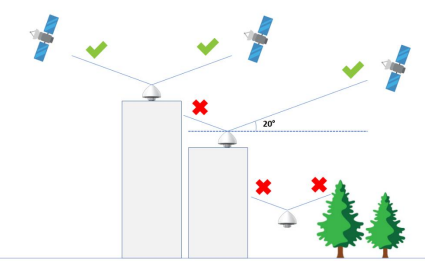
The GPS antenna must have a clear view from the sky. The mounting location of the antenna should be cleared from objects that could obstruct the satellite visibility from straight overhead to within 20 degrees of the horizon in all directions, as illustrated below: