Modbus flow example
As of TAO version 2.1.0, a sample Modbus flow is provided in Node-Red. It allows LoRaWAN sensors to expose data inside an built-in slave Modbus server. This server is available on the standard tcp port 10502.
The sample requires that all uplinks are published in the internal MQTT topic /uplink-topic.
This is the case with the default 'UPLINK / DOWNLINK' flow provided during the installation.
Loading the modbus-sample flow
From the Node-RED flow editor:
Click
 at the top right corner, then select Import.
Select Actility library -> flows -> modbus-sample.js
Click the Import button
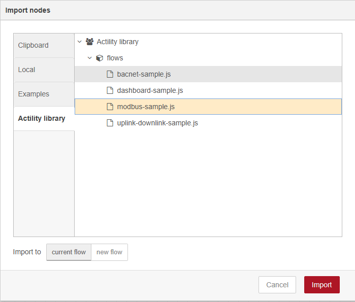
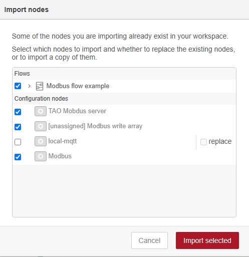
On the incoming warning message, click View nodes....

On the "Import nodes" window, ensure that "Modbus flow example" is checked, then click Import selected.
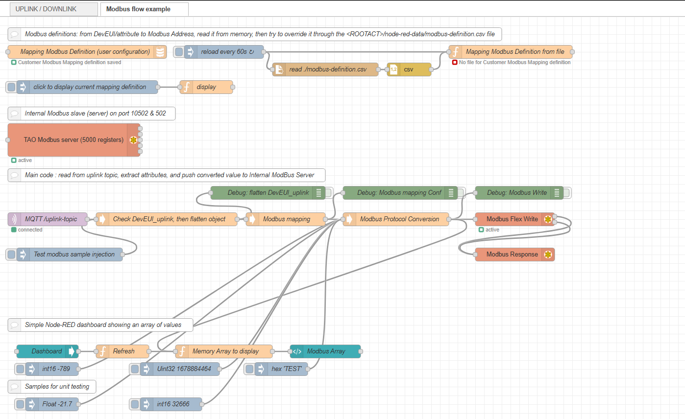
-> the new "Modbus flow example" tab has been added in the editor:
Deploy
 the new flow. To learn more, see
Node-RED deploy.
the new flow. To learn more, see
Node-RED deploy.
Uplink packets
Process
The process steps are described hereafter. Only the first step requires manual configuration, other steps are automatically run by TAO.
Define a mapping table that specifies, for each LoRaWAN sensor, which property should be extracted, what encoding algorithm must be applied and at which location it must be written on the modbus holding register array.
This is a manual step, described in details in the Modbus mapping section below.
Receive uplink messages from LoRaWAN sensors and decode the hexadecimal payload with the proper driver (if any).
Process the decoded payload and convert each selected property into Modbus values (using the mapping table).
Expose each value to an internal Modbus server.
The sample follows these steps:
The uplink message is extracted from the '/uplink-topic' of the internal MQTT server (MQTT input node). All messages are injected in the 'Check DevEUI_uplink, then flatten object' function that parses the DevEUI_uplink and provides the attribute name property conversion.
The message is then passed to the 'Modbus mapping' function followed by the 'Modbus Protocol Conversion' function that injects Modbus write operations to the 'Modbus Flex Write' node. All write operations targets the internal 'TAO Modbus server'.
Customization
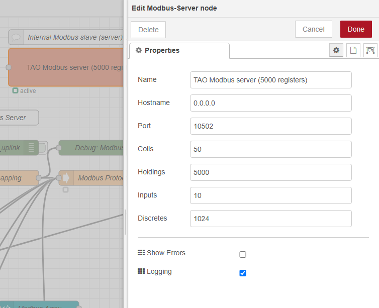
Modbus server

The modbus server is configured to listen on TCP port 10502, you can change it to port 11502.
Modbus mapping
To define the mapping, you may use one of the following methods:
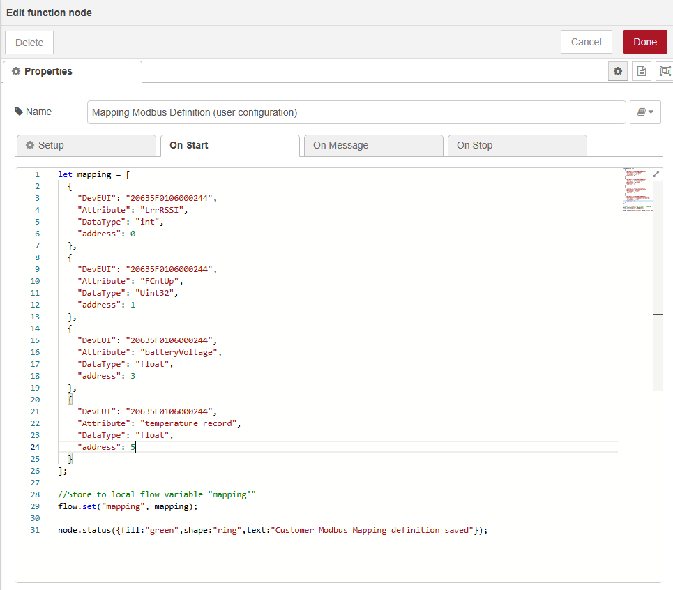
Either directly modify an in-memory array inside the 'Mapping Modbus Definition (user configuration)' node:

Or upload the 'modbus-definition.csv' file inside the Node-Red data folder. A sample is given here. To learn more about how to upload your file, see Uploading a file to the Node-RED data folder.

noteThe second method has the precedence over the first method: during its execution, the flow will first load the mapping from the 'Mapping Modbus Definition (user configuration)', and overwrites it by the content of the 'modbus-definition.csv' if the file exists and is parsable. The flow regularly tries to reload the file (every 60s).
For each property that you want to extract from the uplink message, you have to provide an object composed of the following fields:
DevEUI: is the LoRaWAN sensor's DevEUI.
Attribute: the attribute name property extracted from the LoRaWAN uplink. See below to learn more about the Attribute properly conventions.
DataType: the Modbus operation to apply. See below to learn more about the supported types.
address: modbus register number location.
Attribute property conventions
The first level properties under DevEUI_uplink are available as is:
- DevEUI_uplink.LrrRSSI -> LrrRSSI
The property includes the path below payload, points, each part is added using the dot
.separator.The attributes in DevEUIuplink.payload are accessible in first level, sub paths are recreated using underscore (''):
- DevEUI_uplink.payload.batteryVoltage -> batteryVoltage
- DevEUI_uplink.payload.levels.power -> levels_power
The attributes in DevEUIuplink.points are accessible in first level, sub paths are recreated using underscore (''):
- DevEUI_uplink.points.temperature.record -> temperature_record.
Supported DataTypes
- 'float': modbus operation is FC 16, write 2 registers : 4 bytes.
- 'int': modbus operation is FC 16, write 1 register : 2 bytes.
- 'uint' or 'uint32': modbus operation is FC 16, write 2 registers : 4 bytes.
- 'hex': modbus operation is FC 16, write n registers : n*2 bytes, (for "0A0B0C", it will consume 2 registers, first one containing 0A0B, second one containing 000C).
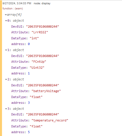
Once you are done, you must press the Click to display mapping definition button.

It will print the mapping on the debug window like so:
Extraction function
If you want to support other DataTypes, or convert decoded payload to one of the DataTypes listed above, contact your support team.
Visualization
Once the flow is running, each extracted data from your LoRaWAN sensors is exposed as modbus values in the holding registers.
You can use a tool like Modbus Doctor to visualize the content :
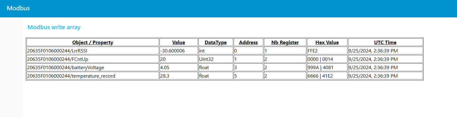
Incoming payload (extract):
DevEUI_uplink: {
  Time: "2024-09-24T13:51:10.920+00:00"
  DevEUI: "20635F0106000244"
  FPort: 17
  ...
  LrrRSSI: -30.600006
  ...
  payload: {
      messageType: "HEARTBEAT"
      trackingMode: "PERMANENT_TRACKING"
      batteryVoltage: 4.05
      ...
  }
  points: {
      temperature: {
        unitId: "Cel"
        record: 28.3
      },
      ...
  }
}
-> We have received a DevEUI_uplink with:
- LrrRSSI measured at -30.6000006
- batteryVoltage at 4.05
- temperature at 28.3
We have the following mapping:
{
"DevEUI": "20635F0106000244",
"Attribute": "LrrRSSI",
"DataType": "int",
"address": 0
},
{
"DevEUI": "20635F0106000244",
"Attribute": "FCntUp",
"DataType": "Uint32",
"address": 1
},
{
"DevEUI": "20635F0106000244",
"Attribute": "batteryVoltage",
"DataType": "float",
"address": 3
},
{
"DevEUI": "20635F0106000244",
"Attribute": "temperature_record",
"DataType": "float",
"address": 5
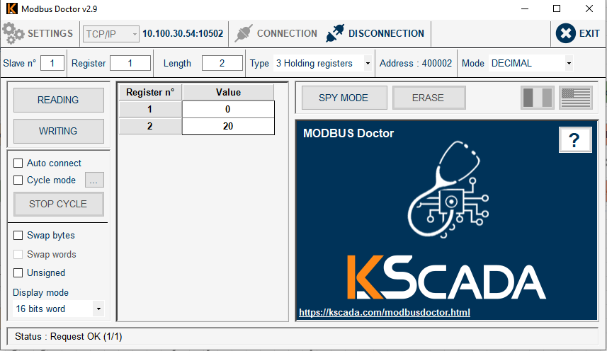
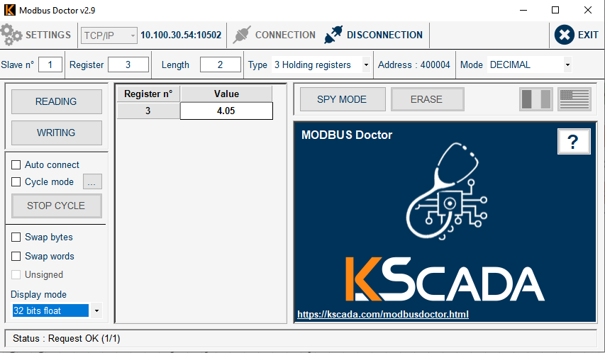
}The corresponding visualization for:
The LrrRSSI : register 0, length 1, mode decimal, 16 bits word:
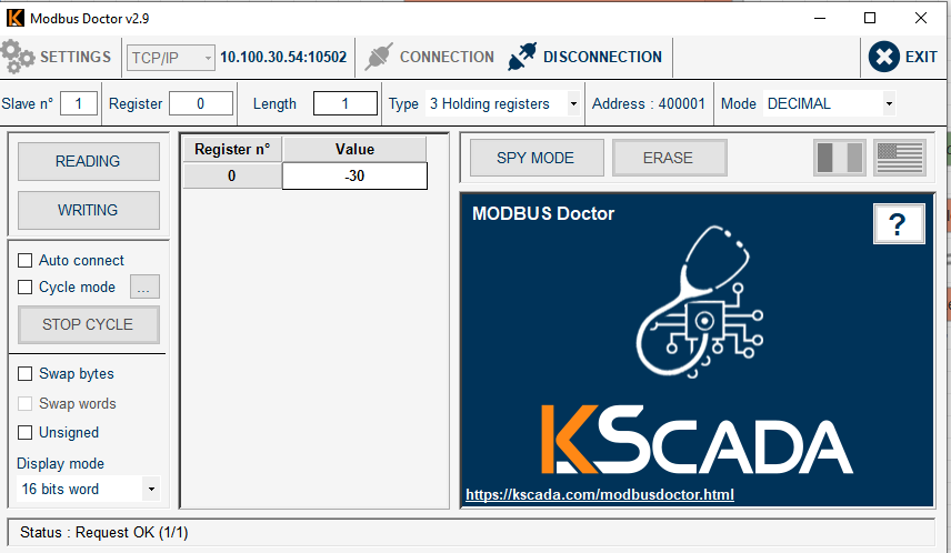
The FCntUp : register 1, length 2, mode decimal, 16 bits word:
The batteryVoltage : register 3, length 2, mode decimal, 32 bits float:
Dashboard
A dashboard is available at the standard http://\<box ip>:1323/node-red/ui url, it sums up the latest entries.
Downlinks
Downlinks via modbus is not currently implemented. However, you can still send downlink messages via the MQTT downlink-topic, as described in MQTT usage.