Setting up the Modbus dataflow
The Modbus dataflow allows you to automatically expose the data of your LoRaWAN devices inside an built-in slave Modbus server.
By default, this server is available on the standard TCP port 10502. If needed, you may change the port in Node-RED, as described in Modbus server customization.
This dataflow supports the four Modbus data types, they may be set as inputs/outputs for uplink/downlink properties respectively:
- Holding Register (noted 'HR'): 16 bits, typically used for numbers and strings having read/write access (UL/DL)
- Input Register (noted 'IR'): 16 bits, typically used for numbers and strings having read-only access (UL only)
- Discrete Input (noted 'DI'): binary input, read-only (UL only)
- Coil (noted 'C'): binary output, read-write (UL/DL)
Starting TAO v2.7.0, the mapping of LoRaWAN sensor data into Modbus registers is fully automated.
If Modbus was already activated on your TAO before upgrading to release 2.7.0 (or higher), your old Modbus dataflow (based on manual mapping through CSV import) is kept by default for sake of backward compatibility.
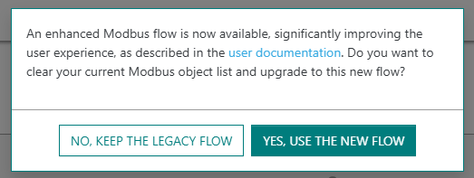
If you want to switch to the new dataflow (based on automated mapping), you must deactivate your
current Modbus dataflow, then reactivate it and confirm your action by clicking YES, USE THE NEW FLOW.
Doing so will reset your current Modbus object list.
Each device exposing data over Modbus is automatically assigned a Unit-ID.
Since the Modbus protocol limits the Unit-ID range to [1 - 247], TAO does not
allow Modbus over more than 247 LoRaWAN devices.
When this limit is reached, devices on which the Modbus activation has failed show an error on the user interface, during unitary or bulk device provisioning.
Main steps
The following steps describe how to setup the Modbus dataflow:
-
From the left panel of the user interface, go to Dataflows.
-
In the Modbus tab, activate the Modbus flow if it is not already the case, by clicking ACTIVATE MODBUS.
tipYou may show/hide the content of each widget in the Modbus tab, by clicking
 /
/ respectively, near
the widget title.
respectively, near
the widget title. -
In the SETTINGS widget, you may personalize the byte ordering for each register size to match your deployment conditions.

Additionally, you may freely define which LoRaWAN metadata are exposed as Modbus registers, by activating the related switch in the user interface:
- RSSI is the Received Signal Strength Indicator of each LoRaWAN uplink packet. RSSI measures the overall signal strength within the radio channel's bandwidth, summing up the useful signal, the interference and the background noise. RSSI is expressed in dBm.
- SNR is the Signal to Noise Ratio of each LoRaWAN uplink packet. It provides a reliable estimation of the quality of the uplink reception. SNR is expressed in dB.
- FCntUp is the frame counter of each LoRaWAN uplink packet.
- SpFact is the Spreading Factor of each LoRaWAN uplink packet. SF7 corresponds to the fastest data rate while SF12 corresponds to the slowest data rate.
-
In the OBJECT DEFINITION widget, choose which device models should expose their measurement properties (also called points) as Modbus registers. For more details, see Updating object definition.
-
The OBJECT LIST widget displays the list of Modbus objects currently defined in your TAO. To learn more, see Viewing the Modbus object list.
Updating object definition
You must define which devices should expose their measurements over Modbus protocol. If you have not added any object definition, TAO will not expose any Modbus objects for your LoRaWAN sensors.
To simplify the user experience, this definition is not made specifically for each LoRaWAN device: you just need to set it up for each device model of interest, this definition then applies to all the LoRaWAN devices associated with this model.
There are two modes of object definition, depending on the device model:
-
Advanced definition
-
As of TAO v2.7.0, this mode applies to the following device models:
- Enless (all models)
- Watteco (all models)
- Thermokon (all models)
- MClimate Vicki
Native support of other device manufacturers will be progressively added in future releases.
-
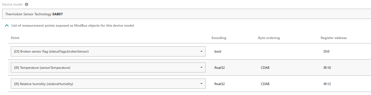
In this mode, users must choose which points are exposed on Modbus. For points encoded as unsigned integers, the user may also choose between 16 and 32 bits according to their need.
noteYou should define at least one point per selected device model. If a device model is selected without any points, TAO will not expose any Modbus objects for the devices associated with this model.
Example:
-
This mode allows sending downlink commands over Modbus protocol. Downlink points use one of the following types: holding register (HR) or Coil (C). To learn more about using Modbus for downlink, see Sending downlink commands with Modbus.
-
-
Basic definition
-
This mode applies to all the LoRaWAN models having a valid payload driver in TAO, but they do not yet support the advanced definition mode.
-
In this mode, users cannot choose which points are exposed on Modbus: all the available measurement points are automatically exposed as Modbus objects. Available points are retrieved from uplink payloads reported by each device. Hence, Modbus objects are created on the fly, when the device starts sending uplink packets.
-
Sending downlink commands over Modbus protocol is not supported in this mode. You may use MQTT for downlink transmission.
-
Use the ![]() button, available at the top-right corner of the OBJECT DEFINITION widget,
to export your current object definition, then import it on other TAO servers without manually defining it each time.
button, available at the top-right corner of the OBJECT DEFINITION widget,
to export your current object definition, then import it on other TAO servers without manually defining it each time.
-
To add definition for a new device model, click ADD OBJECT DEFINITION.
-
Choose a Device model, from the list of models currently used by the devices you already added.
-
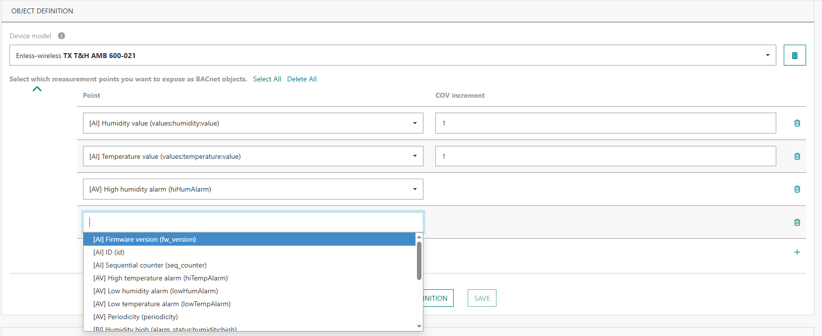
If the model supports the advanced definition mode, you will be asked to select the measurement points that you want to expose as Modbus objects.
Tips- Start typing in the search area to easily find a point.
- Click Select All if you want to add all the points supported by this model.
Then, you may select those that do not want to keep and remove them by clicking
 .
.
Each point is preceded by its type:
- [HR] for Holding Registers
- [DI] for Discrete Inputs
- [IR] for Input Registers
- [C] for Coil
-
To add more points, click
 at the bottom-right of the table.
 -
When you are done, click SAVE.
-
At any time, you may update your mapping by clicking EDIT.
Sending downlink commands with Modbus
Sending downlink commands through Modbus is natively supported for all the device models that support the advanced definition mode. See the full list in the previous section.
Downlink commands use the LoRaWAN confirmed mode to ensure reliable delivery to end-devices, they are automatically retransmitted by TAO in case of transmission/reception failure. Up to 5 commands may be concatenated into the same LoRaWAN downlink packet.
For devices supporting the LoRaWAN class C mode, when a downlink actuation command is sent to the device, other commands cannot be sent until the first command is completely processed, either with a positive acknowledgment by the device or when the processing is eventually aborted after 5 transmission attempts without any acknowledgment.
Viewing the Modbus object list
The Modbus object list, showing all the Modbus points with their current value, is displayed in the
OBJECT LIST widget of the Modbus tab.
The timestamp of the last update of each point is also displayed in this list.
"Never" means that the default value of the point is displayed because
the sensor has not yet reported any actual measurement for it.
You may filter this list by device name, device EUI, object name, Modbus Unit-ID or register address. Searching in the middle of a string is allowed.
Click ![]() at the top-right corner of this widget
to export the list of (filtered) Modbus points.
at the top-right corner of this widget
to export the list of (filtered) Modbus points.
Replacing a device
You may replace an old LoRaWAN device by another one, while reusing the Unit-ID and register addresses of your old device for the new one. This may be needed if a device becomes defective due to hardware or software problems (such as battery issues); in this case, you can easily replace it without changing the client-side Modbus mapping.
Follow these steps to replace a device:
- Add the new device to your ThingPark All-in-One, as described in Provisioning your devices.
- From the left panel, click Dataflows then go to the bottom of the Modbus tab, in OBJECT LIST OPERATIONS widget, then click Replace.
- Fill the DevEUI of your old device and new one one, then click Validate.
- When you are done, delete the old device from TAO:
- From the left panel, click Devices, then search for the device by its DevEUI,
- Click ... on the last column of the list, then Delete and confirm your action.