Networking
Overview
The networking part can handle both LoRa and cellular based networks. It is designed as follows:
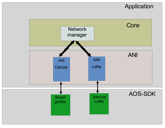
Network manager
The network manager drives the LoRaWAN and the cellular network interfaces (ANI) and selects which one is active at a given time. The cellular and LoRaWAN networks cannot be active at the same time due to antenna sharing.
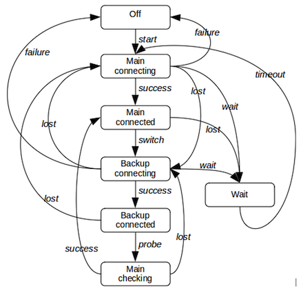
The network connectivity management is built around a FSM.
Operations
The network manager selects the active WAN connectivity technology according to the net_type_selection parameter:
- lorawan_only: The network manager uses only LoRaWAN. It never switches to the cellular network.
- cell_only: The network manager uses only the cellular network. It never switches to LoRaWAN.
- lorawan_fallback_cell: The network manager uses LoRaWAN by default. In case of LoRaWAN network loss, it switches to the cellular network and periodically tries to reconnect to the LoRaWAN network. LoRaWAN is considered as the main network, while the cellular is considered as the backup network.
- cell_fallback_lora: The network manager uses the cellular network by default. In case of cellular network loss, it switches to the LoRaWAN network and periodically tries to reconnect to the cellular network. Cellular is considered as the main network, while LoRaWAN is considered as the backup network.
When the network manager is in fallback mode (backup network active), it periodically probes the primary network: it suspends the backup network operations and attempts to reconnect the main network.
FSM states
- Off: Network manager is down.
- Main-connecting: The connection to the main network is in progress
- Main-connected: The main network is connected
- Backup-connecting: The connection to the backup network is in progress
- Backup-connected: The backup network is connected
- Main-checking: The backup network is suspended. The network connection manager tries to reconnect the main network.
- Wait: Wait for the end of the inter-connection duration
FSM events
- start: Start the networking.
- failure: Unrecoverable failure (SIM error for example in case of cell-only). In case of both networks used failure is generated only if both networks have unrecoverable failure.
- lost: Network lost or fails to connect (recoverable failure)
- switch: Switch between the main and backup network. This event is generated when the main network is lost and the network switching is allowed by configuration. If not allowed to switch, this event is not generated and a lost event is sent to the FSM.
- probe: Start the main re-connection attempt.
- wait: Inter-connection spacing requested. This event is sent only
if the connection spacing timeout is configured and when:
- There is no backup network defined or in permanent error.
- We are in backup-connecting state (meaning that the main network failed), and the backup network also fails.
- timeout: connection spacing timeout
FSM diagram
Application message routing
The network manager offers data several pipes to the application. It maps a given data pipe to a given cellular UDP/TCP socket or a LoRaWAN "socket".
Cellular ANI
The cellular ANI performs the following tasks:
- Drives the cellular driver for the Sequans GM02s module which supports both LTE-M and NB-IOT.
- Manages the cellular connectivity (configuration, network attachment/detachment,).
- Manages the UDP/TCP sockets
- Manages the messages received from the LTE network and forwards them to the network manager.
- Manages the messages sent by application (via the network manager) and forwards them to the network.
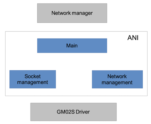
ANI design
The interface with the Network manager is based on direct calls from the Network manager to the ANI and notifications from the ANI to the Network manager via a callback function.
ANI operation
- The Network manager opens the ANI for LTE connectivity
- The request is forwarded to the socket management
- The socket manager opens the cellular network management
- The connection management forwards the connectivity result to the socket management
- On connection success, the socket management opens its socket(s) and informs the Network manager of the success.
- On connection failure, the socket management informs the Network manager of the failure.
- Once connection is established and a network failure is reported by the connection management, the socket management closes its socket(s) and informs the Network manager.
The ANI logic drives the network management subsystem and the socket management subsystem.
Network management
The cellular network interface requires a SIM card that contains operator information, credentials, and service profiles. Depending on the Abeeway hardware platform, up to two SIMs may be available:
-
SIM0 – the physical micro-SIM card inserted into the PCBA SIM tray.
-
SIM1 – available only on configurations where an eSIM is soldered onto the PCBA (special-order variants).
Cellular connection management
Overview
The modem notifies the status of the connection as well as its establishment through unsolicited notifications, called "CEREG URC" :
- 0: No search
- 1: Registered against the home network
- 2: Searching
- 3: Registration denied
- 4: Out of network coverage
- 5: Connected via roaming
- 80: Network temporarily lost.
The cellular connection management also enables the SIM status unsolicited notifications :
- 0: No SIM card detected.
- 1: SIM under initialization
- 2: SIM locked (PIN or PUK required)
- 3: SIM invalid
- 4: SIM card failure
- 5: SIM card ready
- 6: PH-NET pin required
- 7: Phone-to-SIM password required
- 8: Invalid SIM card in PS (Packet Switched) domain
- 9: Invalid SIM card in PS (Packet Switched) and CS (Carrier Switched) domain
- 10: Invalid SIM card in CS (Carrier Switched) domain
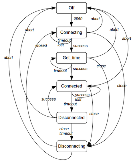
The cellular connection management is based on the finite state machine (FSM) described below.
Contextual variables
- state: Current state of the FSM
- timer: Timer used by the FSM
- reason: Disconnection reason.
- connected_once: Boolean indicating whether cellular network has been connected at least once.
FSM states
- Off: The modem is shutdown
- Connecting: The modem is attaching to the network.
- Get_time: Request the UTC time to the network.
- Connected: The modem is attached to the network.
- Disconnected: The network has been lost.
- Disconnecting: The modem is being disconnected.
- Suspending: The modem is being suspended.
- Suspended: The mode is suspended.
FSM events
- open: Administrative event sent by the network manager to open the cellular connection or when the suspended state should be left.
- close: Event sent by the network manager or by the ANI itself if there are no more sockets open.
- timeout: Timer elapsed.
- success: Successfully connected and attached to the network (Got CEREG 1 or 5).
- get_time: Get time request successfully answered.
- lost: Network temporary lost (CEREG=80).
- closed: Sent to the FSM once the disconnection is complete
- abort: Abort requested by the manager to shutdown the network (non graceful close).
State diagram
Notes
- In the state Connecting: Each timeout event resets and restarts the GM02S and increases the attempts counter. After n attempts, the abort event is generated.
- In the state Get_time, if the network has been connected at least once, the state is skipped.
- In the state Get_time, the request can be sent up to 3 times. The timeout event for this state is generated each 15 s. If the request definitely fails after 3 attempts, the FSM moves in the connected state (since there can be other sources to get the UTC time, e.g LoRa or GPS).
- In the state Connected, if a lost event occurs, a timer is started to allow the modem to recover the network. When it elapses, the event timeout is generated.
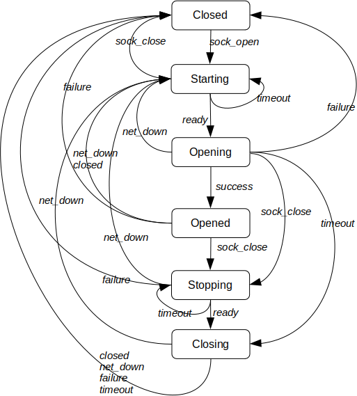
Cellular socket management
The socket management is built around the finite state machine (FSM) described below. The FSM is replicated for each configured socket.
The GM02s driver is able to process only one socket at a time, so the cellular socket management serializes the opening/closing socket requests.
The cellular network management sends the sock_open event to the socket FSM whenever the cellular network manager enters the Connected state and sends the net_down event whenever the network manager reaches the Off state.
FSM states
- Closed: The socket is closed.
- Starting: The socket should be open and is waiting for either the network up or the GM02S ready to send socket requests.
- Opening: The socket is being opened.
- Opened: The socket is open. Data traffic can flow
- Stopping: The socket should be close and is waiting for the GM02S ready to send socket requests.
- Closing: The socket is being closed.
FSM events
- sock_open: Event issued to open the socket
- sock_close: Either an administrative close request has been issued either by the above-layer/configuration or due to a failure.
- ready: Event issued when the network is up or when the GM02S is ready to accept requests.
- net_down: Event issued by GM02S driver indicating that the network is down.
- success: Event triggered by the GM02S driver indicating that the socket opening is successful.
- failure: Event triggered by the GM02S driver indicating that the socket opening failed or if the socket has been remotely closed or if a driver socket related error occurs.
- closed: Event triggered by the GM02S driver indicating that the socket is closed.
FSM diagram
Notes
- The ready event is sent by the Network FSM when it reaches the connected state.
- The net_down event is generated by the Network FSM when the state Off is entered.
- In state Opened, the data traffic can flow if and only if the network FSM is in state Connected.
- Only one socket gets the ready event at a time.
- The net_down event is sent to all sockets.
Dynamic configuration
To be properly configured the socket should have at least the destination IP/URL address and the destination port.
When configured and the network opened but not connected, the socket FSM goes in state starting and remains in this state until the network is reachable.
When the network is connected and the socket is unconfigured (port = 0 or no IP address), the socket moves to the close state. In addition if there is no more sockets opened, the network is shutdown.
Transmission over a socket
Each socket has its own transmission queue handling up to 5 messages.
In order to optimize power consumption, the actual transmission follows the rules:
- Send ASAP if the network is connected and the modem is active (not in deep sleep).
- Postponed by the TX aggregation timer if the network is connected and the modem is sleeping and the transmission queue is not almost full (less than 4 buffers)
- Send ASAP if the network is connected and the queue is almost full (greater than or equal to 4 buffers including the new one)
- Send ASAP when the aggregation timer elapsed and the network is connected
- Postponed until recovery if the network is disconnected.
Note
- When the opportunity of transmission occurs, all buffers are sent.
- When the transmission queue becomes full (can arise if network disconnected), the oldest message is removed from the queue.
- Each socket has its own TX aggregation timer (and configuration)
LoRaWAN ANI
The LoRaWAN ANI module controls the LoRaWAN part of the LR1110. It sits on the top of the LoRaWAN service. As of today, only the LoRaWAN class A is supported. Next releases will address also class B.
ANI operation
- Attach to the LoRaWAN network (Join sequences).
- Leave the network (useful when LTE is also present on the board). Note that both LTE and LoRa cannot run at the same time (antenna sharing).
- Support multiple lora-sockets. Each sockets are characterized by a specific UL port and a specific DL port. The term lora-socket (which is not an usual UDP/TCP socket) is generalized by analogy to TCP/IP over LTE.
- As LTE, each lora-socket has it own queue to send traffic (uplinks).
- Support multiple type of transmission strategies (ADR, random, custom, and so on)
- Support single or dual transmissions.
- Probing the network once joined
- Send periodic heatbeat uplinks to trigger downlinks.
Network probing
Probing process is driven by two parameters per motion state:
lorawan_probe_period_static/lorawan_probe_period_motion: Interval (seconds) between link-check requests.lorawan_probe_max_attempts_static/lorawan_probe_max_attempts_motion: Number of consecutive failed link-check requests after which the LoRaWAN network is considered lost.
Probing can be configured to work in both motion states (static and motion) or only in one of them, or be completely disabled :
- To enable probing for both motion states, set
lorawan_probe_max_attempts_motionandlorawan_probe_max_attempts_staticto non-zero values. - To enable probing only when the device is static, set
lorawan_probe_max_attempts_motionto 0 andlorawan_probe_max_attempts_staticto a non-zero value. - To enable probing only when the device is in motion, set
lorawan_probe_max_attempts_staticto 0 andlorawan_probe_max_attempts_motionto a non-zero value. - To disable probing, set a value of 0 for both
lorawan_probe_max_attempts_staticandlorawan_probe_max_attempts_motion.
When the configured probe period elapses (lorawan_probe_period_static or lorawan_probe_period_motion, depending on the motion state), the device sends a link-check request (LoRaWAN LinkCheckReq).
If the number of consecutive failed link checks reaches the configured limit (lorawan_probe_max_attempts_static / lorawan_probe_max_attempts_motion), the LoRaWAN network is considered lost.
Please note that probing period is compared to a total accumulated time since the last probe. Even if the probing period changes, following a state change, the timer will remain the same. In other words, imagine the following scenario:
lorawan_probe_period_staticis set to 3600s.lorawan_probe_period_motionis set to 300s.- The device has been static for 1800s
- Then the device starts to move.
At that time, accumulated timer equals 1800s which is more than lorawan_probe_period_motion. Therefore, a probe is immediately sent.
If probing concludes that the network is lost, the ANI module attempts to rejoin.
Some LoRaWAN network servers will not make the application server aware of LinkCheckReq commands sent by a device. This has no consequences for the device but may cause confusion when troubleshooting as it can be falsely interpreted as packet loss if you are logging uplinks from the application server.
Join process
AT3 uses the LBM randomization and datarate distribution (which consists of an array of 16 entries). Each entry is a datarate. The LBM selects randomly one entry at a time. Once used, the entry is tagged to avoid reusing it. AT3 fills the array as follow:
- Non US915 regions: The sequence {DR0, DR1, DR2} is repeated 5 times. The last entry is set to DR0.
- US915: The sequence {DR0, DR0, DR0, DR0, DR0, DR0, DR4} is repeated twice. The last entry is set to DR0.
In practice, on EU868 region, the Join request uses SF 10/11/12 randomly
- During the first hour , 35 Join requests are sent out, randomized with an interval of 50sec, 1mn30s and 2mn40s
- During the next 10 hours, 38 Join Requests are sent out, randomized with an interval of 6mn22s, 13mn50s and 24mn50s
- At the 11th hours, around 9 Join Requests per day are sent out, randomized with an interval of 1h; 2h17mn and 4h7mn
During this process, a connection timer is started if parameter lorawan_cnx_timeout is not null. Once the timer elapses, a timeout event is sent to the FSM and a LoRa leave is done.
If net_reconnection_spacing is not set to 0, the new join attempt will be deferred by the net_reconnection_spacing period. Note that after each reconnection period spacing the back-off algorithm is reset, therefore the impact on battery can be significant if a network is not available (in case you want to ship devices in join mode, prefer configurations that operate on LoRaWAN only, and reconfigure via the network after joining).
The ANI is built around the following FSM.
FSM states
- Shutdown: Network not joined.
- Joining: The join process is in progress.
- Idle: Network joined but not accessible (e.g. LTE is active).
- Active: Network accessible (joined and no LTE).
FSM events
- start: Start the join process or resume the LoRa activity
- suspend: Suspend LoRa
- timeout: Timer expiry
- failure: Unrecoverable failure (no LoRa socket)
- success: Join success
- lost: Network probing failure.
- abort: Leave and stop the network.
FSM diagram
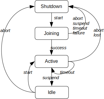
The timeout event in the active state is triggered by the network probing timer, which triggers a link-check request.
Operational modes and configuration
This section covers the networking configuration as well as the operational modes. Relevant configuration is handled by the dedicated configuration groups. Note that in case of non LTE capable trackers, the cellular configuration group is not accessible and the network group has a reduced parameter set.
Configuring LoRaWAN
LoRaWAN is configured via the LoRaWAN parameter group. The relevant parameters are:
net_selection: Network selection. Use value 0 (LoRaWAN only).net_reconnection_spacing_static/net_reconnection_spacing_motion: Interval (seconds) between network-down detection and the next reconnection attempt (new join).lorawan_cnx_timeout: Maximum time budget to successfully join a LoRaWAN network. After this delay, the LoRaWAN network is considered down. A value of 0 lets the join mechanism run indefinitely (join attempts back off exponentially as mandated by the LoRaWAN specification).lorawan_heartbeat_period: Period (seconds) for the heartbeat timer. When it elapses, a heartbeat uplink is sent, opening the Class-A RX1/RX2 windows for downlinks. A value of 0 disables the timer. The timer restarts whenever any uplink is sent.
The associated 'heartbeat' notification must also be enabled via parameter core_notif_enable.
lorawan_probe_max_attempts_static/lorawan_probe_max_attempts_motion: Number of consecutive failed link-check requests after which the LoRaWAN network is considered down. The periodic link-check mechanism starts only after a successful join.
lorawan_probe_max_attempts_staticmust be ≥lorawan_probe_max_attempts_motion.lorawan_probe_period_static/lorawan_probe_period_motion: Interval between link-check requests.
The _static parameters are used when the tracker is static; the _motion parameters are used when the tracker is in motion.
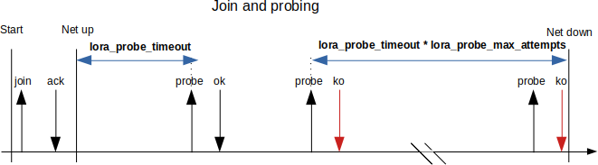
The detection window before declaring the LoRaWAN network down is approximately:
lorawan_probe_max_attempts * lorawan_probe_period (for the current motion state).
After this duration elapses with consecutive failures, the manager leaves the network and attempts to rejoin.
The following diagrams illustrate the various LoRaWAN timers. For simplicity, the _static and _motion suffixes are omitted.

Configuring the cellular network
The cellular network is configured via the cellular parameter group. The relevant parameters are:
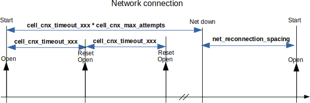
net_selection: Use value 1 (cellular only).net_reconnection_spacing_static/net_reconnection_spacing_motion: Interval (seconds) between network-down detection and the next reconnection attempt.cell_cnx_timeout_static/cell_cnx_timeout_motion: Maximum time budget to successfully connect to the cellular network (per motion state).cell_cnx_max_attempts: Maximum number of consecutive failed connection attempts before the cellular network is reported unavailable to the network manager.
The _static parameters are used when the tracker is static; the _motion parameters are used when the tracker is in motion.
When cell_cnx_max_attempts is exceeded, the manager marks cellular as down and applies the policy defined by net_selection (e.g., retry after net_reconnection_spacing_* or switch per your fallback policy).
The following timing diagram shows the connection processing. For simplicity, the _static and _motion suffixes are omitted.
Configuring main and backup networks
In dual-network configurations, both networks are configured and net_selection defines which one is main and which one is backup.
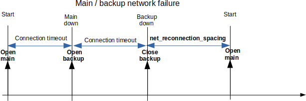
Behavior
- The connection manager attempts to connect to the main network.
- If the main network fails, it attempts to connect to the backup network.
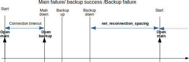
- If both networks fail, the manager waits for
net_reconnection_spacing_static/net_reconnection_spacing_motion(based on motion state), then retries the main network. - While operating on the backup network, the manager probes the main network. After each
net_main_probe_timeout_static/net_main_probe_timeout_motion, it suspends the backup link and tries to reconnect to the main network.- If reconnection succeeds, the main network remains active.
- Otherwise, the backup link is resumed and the probe timer restarts.
During a main-network probe, backup connectivity is suspended (the application cannot send payloads).
Parameters
net_selection- 2: LoRaWAN is the main network; cellular is backup.
- 3: Cellular is the main network; LoRaWAN is backup.
net_reconnection_spacing_static/net_reconnection_spacing_motion
Interval between detecting that both networks are down and the next attempt to reconnect the main network.net_main_probe_timeout_static/net_main_probe_timeout_motion
Interval between main-network probe attempts while the backup network is active.
LoRaWAN-specific and cellular-specific parameters should be set as described in the previous sections (e.g., lorawan_cnx_timeout, cell_cnx_timeout_static / cell_cnx_timeout_motion, etc.).
The following timing diagrams show the connection processing. For simplicity, the _static and _motion suffixes are omitted.
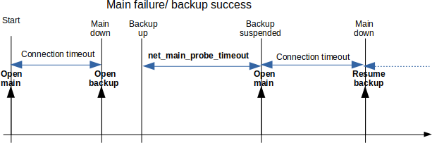
The net_main_probe_timeout duration is also based on the accelerometer state and follows the same management: for each motion state, an independent timer is used to accumulate the total elapsed time in each state.