Version: TAO v2.x

Using Modbus protocol

Starting TAO version 2.1.0, a Modbus flow is provided in Node-Red. It allows LoRaWAN sensors to expose data inside an built-in slave Modbus server. This server is available on the standard tcp port 10502.

The flow requires that all uplinks are published in the internal MQTT topic /uplink-topic. This is the case with the default 'UPLINK / DOWNLINK' flow provided during the installation.

Loading the ModBus flow

caution

This task is only relevant for ThingPark versions 2.1.x.
For ThingPark 2.2.0 onwards, the Modbus flow is directly loaded when you activate the Modbus dataflow in TAO's user interface.
To know the version of your ThingPark Enterprise All-in-One server, hover your mouse on the logo at the top left of the user interface.

Do not reload the Modbus flow if you already have a "Modbus" tab displayed in Node-RED.

From the Node-RED flow editor:

  1. Click at the top right corner, then select Import.

  2. Select Actility library -> flows -> ModBus.json

  3. Click the Import button

  4. On the incoming warning message, click View nodes....

  5. On the "Import nodes" window, ensure that everything except "local-mqtt" is checked, then click Import selected.

    -> the new "Modbus flow example" tab has been added in the editor:

  6. Click at the top right to deploy the new flow. To learn more, see Node-RED deploy.

Process

The process steps are described hereafter. Only the first step requires manual configuration, other steps are automatically run by TAO.

  1. Define a mapping table that specifies, for each LoRaWAN sensor, which property should be extracted, what encoding algorithm must be applied and at which location it must be written on the modbus holding register array.

    This is a manual step, described in details in the Modbus mapping section below.

  2. Receive uplink messages from LoRaWAN sensors and decode the hexadecimal payload with the proper driver (if any).

  3. Process the decoded payload and convert each selected property into Modbus values (using the mapping table).

  4. Expose each value to an internal Modbus server.

The flow follows these steps:

The uplink message is extracted from the '/uplink-topic' of the internal MQTT server (MQTT input node). All messages are injected in the 'Check DevEUI_uplink, then flatten object' function that parses the DevEUI_uplink and provides the attribute name property conversion.

The message is then passed to the 'Modbus mapping' function followed by the 'Modbus Protocol Conversion' function that injects Modbus write operations to the 'Modbus Flex Write' node. All write operations targets the internal 'TAO Modbus server'.

Customization

Modbus server

In the ModBus flow, double-click the TAO Modbus server (5000 registers) node to change its settings:

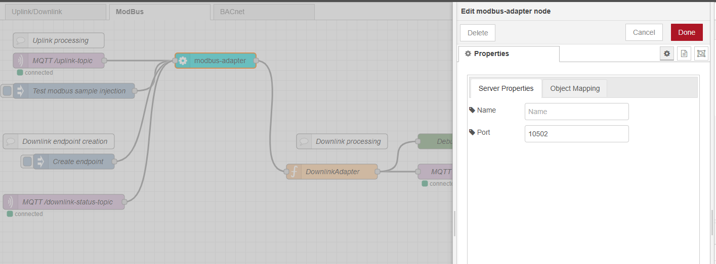
The modbus server is configured to listen on TCP port 10502, you can change it to port 11502.

Modbus mapping

To define the mapping, you must upload the 'modbus-definition.csv' file.

For each property that you want to extract from the uplink message, you have to provide an object composed of the following fields:

  • DevEUI is the LoRaWAN sensor's DevEUI.
  • Attribute refers to the property name as extracted from the LoRaWAN uplink. See below to learn more about setting an attribute for each measured property.
  • DataType: the Modbus operation to apply. See below to learn more about the supported types.
  • address: modbus register number location.

How to set attributes?

Each property - that you need to map to a Modbus object - must be associated with a relevant attribute in your csv mapping file.

To do this, you first need to discover the different properties reported by your LoRaWAN devices in the uplink payloads.

tip

You may use an MQTT client, such as MQTTX or mosquitto_sub, to retrieve the uplink packets reported by your devices and discover which properties are included in their payloads.

Let's take the following example of a device reporting the following uplink packet:

DevEUI_uplink: {
Time: "2024-09-24T13:51:10.920+00:00"
DevEUI: "20635F0106000244"
FPort: 17
FCntUp: 101
LrrSNR: 5.5
...
LrrRSSI: -30.6
...
payload: {
messageType: "HEARTBEAT"
trackingMode: "PERMANENT_TRACKING"
batteryVoltage: 4.05
levels: {
power: 3
state: on
}
},
points: {
temperature: {
unitId: "Cel"
record: 28.3
},
...
}
}

-> We have received a DevEUI_uplink with:

  • LrrSNR measured at 5.5 dB
  • LrrRSSI measured at -30.6 dBm
  • batteryVoltage at 4.05 V
  • power level at 3
  • temperature at 28.3°C

If you want to export the LoRaWAN metadata, such as uplink frame counter (FCntUp), uplink RSSI or SNR, the corresponding attribute shall use exactly the same name as the LoRaWAN metadata, that is to say FCntUp, LrrSNR, LrrRSSI...

Under payload and/or points, the attribute corresponding to each property shall use the property's name. For instance, trackingMode, batteryVoltage... Use underscore _ to represent sub-levels: for instance, levels_power, temperature_record.

Supported DataTypes

  • float: modbus operation is FC 16, write 2 registers : 4 bytes.
  • int: modbus operation is FC 16, write 1 register : 2 bytes.
  • uint or uint32: modbus operation is FC 16, write 2 registers : 4 bytes.
  • hex: modbus operation is FC 16, write n registers : n*2 bytes, (for "0A0B0C", it will consume 2 registers, first one containing 0A0B, second one containing 000C).

Extraction function

If you want to support other DataTypes, or convert decoded payload to one of the DataTypes listed above, contact your support team.

Visualization

Once the flow is running, each extracted data from your LoRaWAN sensors is exposed as modbus values in the holding registers.

You can use a tool like Modbus Doctor to visualize the content :

  • Incoming payload (extract):

    DevEUI_uplink: {
    Time: "2024-09-24T13:51:10.920+00:00"
    DevEUI: "20635F0106000244"
    FPort: 17
    FCntUp: 101
    LrrSNR: 5.5
    ...
    LrrRSSI: -30.6
    ...
    payload: {
    messageType: "HEARTBEAT"
    trackingMode: "PERMANENT_TRACKING"
    batteryVoltage: 4.05
    levels: {
    power: 3
    state: on
    }
    },
    points: {
    temperature: {
    unitId: "Cel"
    record: 28.3
    },
    ...
    }
    }

  • We have the following mapping:

    {
    "DevEUI": "20635F0106000244",
    "Attribute": "LrrRSSI",
    "DataType": "int",
    "address": 0
    },
    {
    "DevEUI": "20635F0106000244",
    "Attribute": "FCntUp",
    "DataType": "Uint32",
    "address": 1
    },
    {
    "DevEUI": "20635F0106000244",
    "Attribute": "batteryVoltage",
    "DataType": "float",
    "address": 3
    },
    {
    "DevEUI": "20635F0106000244",
    "Attribute": "temperature_record",
    "DataType": "float",
    "address": 5
    }
  • The corresponding visualization for:

    • The LrrRSSI : register 0, length 1, mode decimal, 16 bits word:

    • The FCntUp : register 1, length 2, mode decimal, 16 bits word:

    • The batteryVoltage : register 3, length 2, mode decimal, 32 bits float:

Dashboard

A dashboard is available at the standard http://\<box ip>:1323/node-red/ui url, it sums up the latest entries.

Downlinks via modbus is not currently implemented. However, you can still send downlink messages via the MQTT downlink-topic, as described in MQTT usage.